9815 3rd Street Road,Louisville, KY 40272,United States Phone:833-290-1189 Email:info@acquaerpumps.com Web:www.acquaerpumps.com OWNER’S MANUAL Shallow Well Jet Pump Model:SJC100-1 El manual del propietario Bomba de Chorro de Pozo de Poca Profundidad Modelo:SJC100-1 Model:SJC100-1 FOR ENGLISH ................................................................. Pages 02-10 FOR SPANISH .................................................................
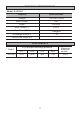
TECHNICAL SPECIFICATIONS Model: SJC100-1 Property Specifications Voltage 115/230V~60Hz Horse Power 1HP Amps 9.6/4.8A Max. Head (ft.) 180 ft. Max. Flow (GPH) 1200@5ft Discharge Size (in.) 1 in. Power cord length (ft.) - PERFORMANCE Model SJC100-1 GPH at 40psi discharge pressure 5 ft. 10 ft. 15 ft. 20 ft.
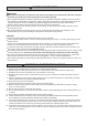
SAFETY INFORMATION WARNING his pump is meant to be used where the vertical lift of water is less than 25 ft. If the well is deeper T than that, you need to purchase a deep well convertible jet pump. Do not pump flammable or explosive liquids such as oil, gasoline, kerosene, ethanol, etc. Do not use in the presence of flammable or explosive vapors. Using this pump with or near flammable liquids can cause an explosion or fire, resulting in property damage, serious personal injury and/or death.
PREPARATION B efore beginning assembly of product, make sure all parts are present.. If any part is missing or damaged, do not attempt to assemble the product. Contact customer service for replacement parts. Estimated Installation Time (New installation): 30-60 minutes Tools Required for Assembly (not included): Wrench, Pliers, Phillips Screwdriver, Thread Tape, PVC Purple Primer, and PVC Cement A ccessories Required for Assembly (not included): P ressure Tank 1 -1/4 in. Foot Valve 1 -1/4 in.
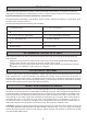
INSTALLATION INSTRUCTIONS N OTE: Use a minimum of 1-1/4” diameter PVC piping for the suction pipe for best performance. A 1 in. MNPT x 1-1/4 in. SLIP adaptor will be needed to make the connection to the pump. WARNING A ll joints and connections must be AIRTIGHT. A single leak will prevent the proper operation of the pump. Wrap thread tape clockwise on all threaded connections. For all non-threaded connections, you must use PVC Purple Primer and PVC Cement to ensure airtight seals.
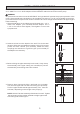
5 . U sing PVC purple primer and PVC cement, attach a1-1/4 in. PVC elbow (not included) onto the rigid PVCpipe extending from the well seal. 5 6 . W rap thread tape around the threads of a male PVC adaptor (not included). Thread the adaptor into the front of the pump (A). 6 7 . U sing PVC purple primer and PVC cement, attach as many sections of rigid PVC pipe and couplings (not included) as needed to connect the male PVC adaptor to the PVC elbow.
1 0. W rap all threads with thread tape. In order for the pump (A) and the pressure tank (not included) to operate properly, the pressure tank needs to be drained of all water BEFORE INSTALLING ITTO THE PUMP. Thread a 10 in. tank tee (not included) or another necessary size tee into the pressure tank. P lug one outlet on top of the tank tee with a 1/4 in. plug (not included) and install apressure gauge (not included) on the other outlet on top of the tank tee. Thread two 1 in.
1 4. T his pump is pre-wired at 230 volts. If the power source is 115 volts, remove the electrical housing cover. Flip the switch to 115 volts. Replace the cover. 14 N OTE: All electrical work should be performed by a licensed electrician. PRESSURE SWITCH INSTALLATION INSTRUCTIONS WARNING! Before wiring the pressure switch, turn off the power source to which you are connecting to avoid potentially life threatening electrical shock.
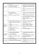
Problem Possible Cause Corrective Action Pump does not start or run 1. 2. 3. 4. 5. Power off Blown fuse or tripped breaker Faulty pressure switch Motor overload tripped Wires are connected incorrectly Pump will not prime 1. Not enough water 2. Air trapped in the pipe 3. Water level in well is below foot valve 4. Foot valve is plugged or leaks 1. Stop motor; remove pressure gauges or prime plug; fill housing pipes with water 2. Adjust the pump's height so that the pipe slopes away from the pump 3.
PARTS DIAGRAM 5 7 4 3 1 2 6 PARTS LIST Part No.
9815 3rd Street Road,Louisville, KY 40272,United States Phone:833-290-1189 Email:info@acquaerpumps.com Web:www.acquaerpumps.com OWNER’S MANUAL Shallow Well Jet Pump Model:SJC100-1 El manual del propietario Bomba de Chorro de Pozo de Poca Profundidad Modelo:SJC100-1 Modelo:SJC100-1 FOR ENGLISH ................................................................. Pages 02-10 FOR SPANISH .................................................................
ESPECIFICACIONES TÉCNICAS Modelo: SJC100-1 Propiedad Especificaciones Voltaje 115/230V~60Hz Caballo de fuerza 1HP Amperios 9.6/4.8A Max. Cabeza(m) 55m Max. Flujo(LPM) 75 tamaño de la descarga 1 in. Longitud del cable eléctrico - RENDIMIENTO Modelo SJC100-1 LPM de agua a un total de metros de cabeza de 40 psi 1.5m 3m 4.
INFORMACIÓN DE SEGURIDAD ADVERTENCIA Esta bomba está destinada a ser utilizada en la elevación vertical del agua es inferior a 25 pies. Si el pozo es más profundo que eso, usted necesita comprar una bomba convertible de chorro de pozo profundo. No bombee líquidos inflamables o explosivos, tales como aceite, gasolina, queroseno, etanol, etc. No utilice en presencia de vapores inflamables o explosivos.
PREPARACIÓN A ntes del montaje del producto, asegúrese de tener todas las piezas. Si alguna parte falta o está dañada, no intente montar el producto. Póngase en contacto con el servicio al cliente para piezas de repuesto.
INSTRUCCIONES DE INSTALACIÓN N OTA:Use tubería de PVC de diámetro mínimo de 1-1 / 4 " para la tubería de succión para un mejor rendimiento. S e necesitará un 1 pulg. MNPT x 1-1 / 4 pulg. SLIP adaptador para hacer la conexión a la bomba. ADVERTENCIA Todas las juntas y las conexiones deben ser HERMÉTICAS. Una sola fuga impedirá el correcto funcionamiento de la bomba. Envuelve el hilo cinta de las agujas del reloj en todas las conexiones roscadas.
5 . U sando cebador púrpura de PVC y cemento de PVC, adjunte un 1-1 / 4 pulg. codo de PVC (no incluido) en el tubo de PVC rígido que se extiende desde el sello del pozo. 5 6 . W rap thread tape around the threads of a male PVC adaptor (not included). Thread theadaptor into the front of the pump (A). 6 7 . U sando cebador púrpura de PVC y cemento de PVC, adjuntar las secciones de rígido de 1 pulg.
1 0. E nvuelva todos los hilos con cinta de hilo. Para que la bomba (A) y el tanque de presión (no incluido) funcionen correctamente, el tanque de presión debe ser drenado de toda el agua ANTES DE INSTALARLO EN LA BOMBA. Enrosque un 10 pulg. Soporte de tanque (no incluido), u otro soporte del tamaño necesario en el diafragma del tanque de presión. C onecte una salida en la parte superior del soporte del tanque con un 1/4 pulg.
1 4. E sta bomba (A) es pre-cableado a 230 voltios. Si la fuente de alimentación es de 115 voltios, retire la tapa de la caja eléctrica. Active el interruptor de 115 voltios. Vuelva a colocar la cubierta. 14 N OTA: Todo el trabajo eléctrico debe ser realizado por un electricista autorizado.
Problema Causa posible La bomba no arranca o funciona 1. Sin batería 2. Fusible fundido o se disparó el disyuntor 3. Interruptor de presión defectuoso 4. sobrecarga del motor actuada 5. Los cables están conectados de forma incorrecta 1. Encender o llamar a la compañía eléctrica 2. Cambiar el fusible o reiniciar el disyuntor 3. Reemplazar el interruptor 4. Dejar enfriar. La sobrecarga se restablecerá automáticamente 5. Seguir las instrucciones para el cableado de la bomba. 1. No hay suficiente agua 2.
DIAGRAMA DE PIEZAS 5 7 4 3 1 2 6 LISTA DE PARTES Número de pieza Descripción 1 cuerpo de la bomba 2 canal de intervalo 3 cubierta de drenaje 4 impulsor 5 motor 6 sello mecánico 7 O anillo 20