B406-4 EMERGENCY LOCATOR TRANSMITTER Description, Operation, Installation and Maintenance Manual This manual includes data for the equipment that follows: Component Part No. Model No. Emergency Locator Transmitter 453-5004 B406-4 ACR ELECTRONICS, INC / ARTEX PRODUCTS 5757 Ravenswood Rd, Ft. Lauderdale, FL 33312 Cage Code: 18560 25-62-03 Page 1 of 87 570-5004 Rev.
ACR ELECTRONICS, INC / ARTEX PRODUCTS DESCRIPTION, OPERATION, INSTALLATION AND MAINTENANCE MANUAL B406-4 (453-5004) PROPRIETARY INFORMATION This document contains proprietary information and such information may not be disclosed to others for any purpose, nor used for manufacturing purposes without written permission from ACR Electronics. Information in this manual is subject to change without notice.
ACR ELECTRONICS, INC / ARTEX PRODUCTS DESCRIPTION, OPERATION, INSTALLATION AND MAINTENANCE MANUAL B406-4 (453-5004) RECORD OF REVISIONS REV NO. DCN NO.
ACR ELECTRONICS, INC / ARTEX PRODUCTS DESCRIPTION, OPERATION, INSTALLATION AND MAINTENANCE MANUAL B406-4 (453-5004) THIS IS A BLANK PAGE 25-62-03 Page 4 of 87 JUN 20/13
ACR ELECTRONICS, INC / ARTEX PRODUCTS DESCRIPTION, OPERATION, INSTALLATION AND MAINTENANCE MANUAL B406-4 (453-5004) SERVICE BULLETIN LIST SERVICE BULLETIN NO ISSUE DATE SUBJECT MANUAL REV NO 25-62-03 MANUAL REV DATE Page 5 of 87 JUN 20/13
ACR ELECTRONICS, INC / ARTEX PRODUCTS DESCRIPTION, OPERATION, INSTALLATION AND MAINTENANCE MANUAL B406-4 (453-5004) THIS IS A BLANK PAGE 25-62-03 Page 6 of 87 JUN 20/13
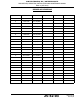
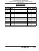
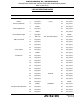
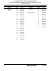
ACR ELECTRONICS, INC / ARTEX PRODUCTS DESCRIPTION, OPERATION, INSTALLATION AND MAINTENANCE MANUAL B406-4 (453-5004) LIST OF EFFECTIVE PAGES SUBJECT PAGE DATE SUBJECT PAGE DATE Title Page 1 Aug 27/12 Description and Operation 30 Aug 27/12 Notices 2 Aug 27/12 (cont.
ACR ELECTRONICS, INC / ARTEX PRODUCTS DESCRIPTION, OPERATION, INSTALLATION AND MAINTENANCE MANUAL B406-4 (453-5004) SUBJECT PAGE DATE SUBJECT PAGE DATE Installation 59 Aug 27/12 Appendix A 77 Aug 27/12 (cont.
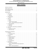
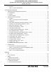
ACR ELECTRONICS, INC / ARTEX PRODUCTS DESCRIPTION, OPERATION, INSTALLATION AND MAINTENANCE MANUAL B406-4 (453-5004) TABLE OF CONTENTS RECORD OF REVISIONS . . . . . . . . . . . . . . . . . . . . . . . . . . . . . . . . . . . . . . . . . . . . . . . . . . . . . . . . . . . . 3 SERVICE BULLETIN LIST. . . . . . . . . . . . . . . . . . . . . . . . . . . . . . . . . . . . . . . . . . . . . . . . . . . . . . . . . . . . 5 LIST OF EFFECTIVE PAGES . . . . . . . . . . . . . . . . . . . . . . . . . . . . . . . . . .
ACR ELECTRONICS, INC / ARTEX PRODUCTS DESCRIPTION, OPERATION, INSTALLATION AND MAINTENANCE MANUAL B406-4 (453-5004) C. Antennas . . . . . . . . . . . . . . . . . . . . . . . . . . . . . . . . . . . . . . . . . . . . . . . . . . . . . . . . . . . . 35 Table 4 Antenna Specifications . . . . . . . . . . . . . . . . . . . . . . . . . . . . . . . . . . . . . . . . . . . . 35 TEST AND FAULT ISOLATION 1. Inspection and Test Regulatory Requirements . . . . . . . . . . . . . . . . . . . . . . . . . . . . . . . . . .
ACR ELECTRONICS, INC / ARTEX PRODUCTS DESCRIPTION, OPERATION, INSTALLATION AND MAINTENANCE MANUAL B406-4 (453-5004) INSTALLATION 1. Regulatory Requirements and Guidelines . . . . . . . . . . . . . . . . . . . . . . . . . . . . . . . . . . . . . . . . . A. TSO C126, Paragraph D . . . . . . . . . . . . . . . . . . . . . . . . . . . . . . . . . . . . . . . . . . . . . . . . . . B. FAA . . . . . . . . . . . . . . . . . . . . . . . . . . . . . . . . . . . . . . . . . . . . . . . . . . . . . . . . . . . . . . . .
ACR ELECTRONICS, INC / ARTEX PRODUCTS DESCRIPTION, OPERATION, INSTALLATION AND MAINTENANCE MANUAL B406-4 (453-5004) 2. Registration . . . . . . . . . . . . . . . . . . . . . . . . . . . . . . . . . . . . . . . . . . . . . . . . . . . . . . . . . . . . . 78 A. Responsibility . . . . . . . . . . . . . . . . . . . . . . . . . . . . . . . . . . . . . . . . . . . . . . . . . . . . . . . . . 78 B. Required Information . . . . . . . . . . . . . . . . . . . . . . . . . . . . . . . . . . . . . . . . . . . . . . . .
ACR ELECTRONICS, INC / ARTEX PRODUCTS DESCRIPTION, OPERATION, INSTALLATION AND MAINTENANCE MANUAL B406-4 (453-5004) LIST OF FIGURES Figure 1. B406-4 ELT and Mounting Frame Assembly. . . . . . . . . . . . . . . . . . . . . . . . . . . . . . . . . . . . . . 28 Figure 2. Remote Switch Panel Assembly Front View . . . . . . . . . . . . . . . . . . . . . . . . . . . . . . . . . . . . . . 29 Figure 3. Buzzer . . . . . . . . . . . . . . . . . . . . . . . . . . . . . . . . . . . . . . . . . . . . . . . . . . . . .
ACR ELECTRONICS, INC / ARTEX PRODUCTS DESCRIPTION, OPERATION, INSTALLATION AND MAINTENANCE MANUAL B406-4 (453-5004) THIS IS A BLANK PAGE 25-62-03 Page 14 of 87 JUN 20/13
ACR ELECTRONICS, INC / ARTEX PRODUCTS DESCRIPTION, OPERATION, INSTALLATION AND MAINTENANCE MANUAL B406-4 (453-5004) INTRODUCTION TASK 25-62-03-990-801 1. Manual Usage SUBTASK 25-62-03-990-001 A. General (1) This manual describes the operation, installation, and maintenance of the Model B406-4 emergency locator transmitter (ELT). The information is provided to ensure initial and continued airworthiness. Information presented in this manual is accurate at time of printing, but is subject to change.
ACR ELECTRONICS, INC / ARTEX PRODUCTS DESCRIPTION, OPERATION, INSTALLATION AND MAINTENANCE MANUAL B406-4 (453-5004) (4) B406-4 ELT installation and maintenance in all other countries must comply with the requirements herein and applicable national airworthiness requirements. (5) The accessories (i.e., remote switch panel and antennas) addressed in this manual are the accessories most commonly associated with the B406-4 ELT.
ACR ELECTRONICS, INC / ARTEX PRODUCTS DESCRIPTION, OPERATION, INSTALLATION AND MAINTENANCE MANUAL B406-4 (453-5004) TASK 25-62-03-990-802 2. Model Description SUBTASK 25-62-03-990-001 A. B406-4 (1) The B406-4 is a type AF (Automatic Fixed) ELT, which transmits on 121.5, 243.0, and 406 MHz. (2) The ELT is enclosed within a multi-piece mounting frame consisting of a mounting tray assembly, protective top cover assembly and mounting frame cap assembly.
ACR ELECTRONICS, INC / ARTEX PRODUCTS DESCRIPTION, OPERATION, INSTALLATION AND MAINTENANCE MANUAL B406-4 (453-5004) TASK 25-62-03-990-803 3. Approvals SUBTASK 25-62-03-990-001 A. B406-4 (1) FAA TSO C126, Type AF (a) The conditions and tests required for TSO approval of this article are minimum performance standards.
ACR ELECTRONICS, INC / ARTEX PRODUCTS DESCRIPTION, OPERATION, INSTALLATION AND MAINTENANCE MANUAL B406-4 (453-5004) Table 1 Environmental Categories Breakdown CATEGORY SECTION DESCRIPTION C1 4.0 Temperature/Altitude - 4.5.4 In-Flight Loss of Cooling B 5.0 Temperature Variation A 6.0 Humidity 204 7.0/8.0 Operational Shock and Crash Safety/Vibration X 9.0 Explosion R 10.0 Waterproofness X 11.0 Fluids Susceptibility X 12.0 Sand and Dust X 13.0 Fungus X 14.0 Salt Spray X 15.
ACR ELECTRONICS, INC / ARTEX PRODUCTS DESCRIPTION, OPERATION, INSTALLATION AND MAINTENANCE MANUAL B406-4 (453-5004) TASK 25-62-03-990-804 4. Frequency Allocations SUBTASK 25-62-03-990-001 A. Application (1) This section addresses the 406.0-406.1 MHz transmitter window and the specific frequency band allocations residing above 406.025 MHz, beginning with 406.028 MHz, which are assigned or reserved within the 406.0-406.1 MHz distress frequency window. SUBTASK 25-62-03-990-002 B.
ACR ELECTRONICS, INC / ARTEX PRODUCTS DESCRIPTION, OPERATION, INSTALLATION AND MAINTENANCE MANUAL B406-4 (453-5004) TASK 25-62-03-990-805 5. List of Acronyms, Abbreviations, and Definitions SUBTASK 25-62-03-990-001 Term Definition AC Advisory Circular – A Federal Aviation Administration (USA) bulletin with special information. For the purposes of this document, the acronym AC does not refer to electrical alternating current. AWG American Wire Gauge – An electrical wire diameter standard.
ACR ELECTRONICS, INC / ARTEX PRODUCTS DESCRIPTION, OPERATION, INSTALLATION AND MAINTENANCE MANUAL B406-4 (453-5004) EUROCAE European Organization for Civil Aviation Equipment – EUROCAE documents are widely referenced as a means of compliance to European Technical Standard Orders (ETSOs) and other regulatory documents. FAA Federal Aviation Administration – The United States government agency for aircraft safety and regulation.
ACR ELECTRONICS, INC / ARTEX PRODUCTS DESCRIPTION, OPERATION, INSTALLATION AND MAINTENANCE MANUAL B406-4 (453-5004) SAR Search and Rescue SCREEN ROOM The term “Screen Room”, within the context of this document, refers to a room designed to suppress RF signals, such that the broadcast of an ELT placed in the screen room cannot reach the SAR satellite system.
ACR ELECTRONICS, INC / ARTEX PRODUCTS DESCRIPTION, OPERATION, INSTALLATION AND MAINTENANCE MANUAL B406-4 (453-5004) TASK 25-62-03-990-806 6. References SUBTASK 25-62-03-990-001 A. Regulatory Documents (1) The following regulatory documents are referred to herein. When referring to such documents, it is the manual user’s responsibility to ensure they are using the latest revision or release of such documents.
ACR ELECTRONICS, INC / ARTEX PRODUCTS DESCRIPTION, OPERATION, INSTALLATION AND MAINTENANCE MANUAL B406-4 (453-5004) (d) DO-183, “Minimal Operational Performance Standards for Emergency Locator Transmitters - Automatic Fixed-ELT (AF), Automatic Portable-ELT (AP), Automatic Deployable-ELT (AD), Survival-ELT (S) Operating on 121.5 and 243.0 MHz” (e) DO-204, “Minimal Operational Performance Standards for 406 MHz Emergency Locator Transmitters (ELT)” SUBTASK 25-62-03-990-002 B.
ACR ELECTRONICS, INC / ARTEX PRODUCTS DESCRIPTION, OPERATION, INSTALLATION AND MAINTENANCE MANUAL B406-4 (453-5004) THIS IS A BLANK PAGE 25-62-03 Page 26 of 87 JUN 20/13
ACR ELECTRONICS, INC / ARTEX PRODUCTS DESCRIPTION, OPERATION, INSTALLATION AND MAINTENANCE MANUAL B406-4 (453-5004) DESCRIPTION AND OPERATION TASK 25-62-03-870-801 1. Description SUBTASK 25-62-03-870-001 A. Functional Overview (1) (2) The ELT automatically activates during a crash and transmits the standard sweep tone on 121.5 and 243.0 MHz. Approximately every 50 seconds, for up to 520 milliseconds (long message protocol), the 406 MHz transmitter turns on.
ACR ELECTRONICS, INC / ARTEX PRODUCTS DESCRIPTION, OPERATION, INSTALLATION AND MAINTENANCE MANUAL B406-4 (453-5004) (7) Aircraft communications transceivers are not capable of receiving 406 MHz transmissions; therefore, the only methods of monitoring the ELT are: (a) The cockpit remote switch panel light, (b) The buzzer, or (c) 121.5/243.0 MHz transmissions, which can be monitored using the aircraft communications transceiver or an AM radio tuned to 121.5 MHz. SUBTASK 25-62-03-870-002 B.
ACR ELECTRONICS, INC / ARTEX PRODUCTS DESCRIPTION, OPERATION, INSTALLATION AND MAINTENANCE MANUAL B406-4 (453-5004) (2) The cockpit-mounted Control Panel G737 (remote switch panel assembly) is a backlit panel comprised of an ELT status indicator light and a control switch, which allows an operator to manually activate the ELT for testing and reset (i.e., deactivate) the ELT. See Figure 2. Remote Switch Panel Assembly Front View. NOTE: The ELT CANNOT be disarmed or disabled from the cockpit.
ACR ELECTRONICS, INC / ARTEX PRODUCTS DESCRIPTION, OPERATION, INSTALLATION AND MAINTENANCE MANUAL B406-4 (453-5004) (5) Five dual-input antennas are approved for use with the B406-4 ELT. Selection of the proper antenna is dependent upon end use, aircraft configuration, speed, and other factors. See Figure 5. Antennas. 110-320 110-333 110-328-01 110-337 110-337-11 Figure 5.
ACR ELECTRONICS, INC / ARTEX PRODUCTS DESCRIPTION, OPERATION, INSTALLATION AND MAINTENANCE MANUAL B406-4 (453-5004) TASK 25-62-03-870-803 2. Operation SUBTASK 25-62-03-870-001 A. Operational Overview (1) See Figure 6. ELT Operational Flow Diagram. (2) A primary feature of the B406-4 ELT is its simplicity of operation. As long as the ELT is connected to the remote switch panel harness ELT connector, such that pins 5 and 8 are jumpered (G-switch loop), it will activate in the event of a crash.
ACR ELECTRONICS, INC / ARTEX PRODUCTS DESCRIPTION, OPERATION, INSTALLATION AND MAINTENANCE MANUAL B406-4 (453-5004) “ACTIVE” state requires a positive switch transition from either the cockpit remote switch, ELT local switch, or G-switch. NOTE: It is possible the G-switch could activate the ELT as the result of severe maneuvers or a very hard landing. (6) To take the ELT from an “ACTIVE” state back to an “INACTIVE” state, a “RESET” must occur. See SUBTASK 25-62-03-870-004.
ACR ELECTRONICS, INC / ARTEX PRODUCTS DESCRIPTION, OPERATION, INSTALLATION AND MAINTENANCE MANUAL B406-4 (453-5004) TASK 25-62-03-870-803 3. Specifications SUBTASK 25-62-03-870-001 A. Environmental and Physical (1) Table 2 lists the environmental and physical specifications of the B406-4 ELT. NOTE: For automatic activation, the higher threshold of 4.5 ft/sec (2.3 g) is specified in accordance with Eurocae ED-62.
ACR ELECTRONICS, INC / ARTEX PRODUCTS DESCRIPTION, OPERATION, INSTALLATION AND MAINTENANCE MANUAL B406-4 (453-5004) SUBTASK 25-62-03-870-002 B. Electrical (1) Table 3 lists the electrical specifications of the B406-4 ELT. Table 3 Electrical Specifications CRITERIA Operating Frequencies Modulation Transmitter Duty Cycle Peak Effective Radiated Power (PERP) Occupied Bandwidth Spurious Emissions Battery PARAMETER CHARACTERISTIC 406.
ACR ELECTRONICS, INC / ARTEX PRODUCTS DESCRIPTION, OPERATION, INSTALLATION AND MAINTENANCE MANUAL B406-4 (453-5004) SUBTASK 25-62-03-870-003 C. Antennas (1) Table 4 lists the specifications of the antennas approved for use with the B406-4 ELT. Table 4 Antenna Specifications PARAMETERS Style CHARACTERISTIC 110-320 110-328-01 110-333 110-337 110-337-11 Rod Blade Blade Blade Blade Frequencies VSWR 121.5, 243.0, 406 MHz 121.5 and 243.0 MHz - 2.0:1 Max. 406 MHz - 1.5:1 Max. 121.5/243.0 MHz - 2.
ACR ELECTRONICS, INC / ARTEX PRODUCTS DESCRIPTION, OPERATION, INSTALLATION AND MAINTENANCE MANUAL B406-4 (453-5004) TEST AND FAULT ISOLATION TASK 25-62-03-750-801 1. Inspection and Test Regulatory Requirements SUBTASK 25-62-03-990-001 A. United States (1) (2) In accordance with FAR Part 91, Subpart C, § 91.
ACR ELECTRONICS, INC / ARTEX PRODUCTS DESCRIPTION, OPERATION, INSTALLATION AND MAINTENANCE MANUAL B406-4 (453-5004) SUBTASK 25-62-03-990-003 C. Other Countries (1) For all other countries, maintenance and testing shall be conducted in accordance with the requirements of applicable national regulatory authorities and the requirements herein, as applicable. Local regulations and requirements shall take precedence.
ACR ELECTRONICS, INC / ARTEX PRODUCTS DESCRIPTION, OPERATION, INSTALLATION AND MAINTENANCE MANUAL B406-4 (453-5004) TASK 25-62-03-750-802 2. Inspection and Test Procedures SUBTASK 25-62-03-990-001 A. Checklist (1) Table 5 provides a list of the ELT inspection and testing requirements, a copy of which may be used as a checklist to verify inspection and test completion. The item numbers in the table correspond to the item identifiers for each task.
ACR ELECTRONICS, INC / ARTEX PRODUCTS DESCRIPTION, OPERATION, INSTALLATION AND MAINTENANCE MANUAL B406-4 (453-5004) SUBTASK 25-62-03-000-001 B. Preparation (1) Remove the ELT in accordance with SUBTASK 25-62-03-010-001 on page 51. (2) Remove the battery pack in accordance with SUBTASK 25-62-03-050-001 on page 52. SUBTASK 25-62-03-220-001 C. Coax Cables and Wiring Connections Inspection – Item 1 (1) Check remote panel harness connector for corrosion bent or broken pins and other damage.
ACR ELECTRONICS, INC / ARTEX PRODUCTS DESCRIPTION, OPERATION, INSTALLATION AND MAINTENANCE MANUAL B406-4 (453-5004) (c) When the total of all known transmissions exceeds one hour; or (d) On or before battery replacement (expiration) date. SUBTASK 25-62-03-750-001 F. G-Switch Functional Check – Item 4 CAUTION: (1) A JUMPER IS REQUIRED TO PERFORM THIS CHECK.
ACR ELECTRONICS, INC / ARTEX PRODUCTS DESCRIPTION, OPERATION, INSTALLATION AND MAINTENANCE MANUAL B406-4 (453-5004) (1) Place the ELT in a container or screen room capable of substantially attenuating RF signals, or the transmitter power output shall be connected to a suitable dummy load to minimize radiation. (2) Use the ELT’s own battery pack as the power source for these measurements. An alternate power source can be used where lengthy servicing, other than the performance tests, is anticipated.
ACR ELECTRONICS, INC / ARTEX PRODUCTS DESCRIPTION, OPERATION, INSTALLATION AND MAINTENANCE MANUAL B406-4 (453-5004) SUBTASK 25-62-03-750-005 J. 121.5/243.0 MHz Power Output Measurement – Item 5c (1) Connect the measuring device, referring to SUBTASK 25-62-03-750-002 on page 40. (2) Activate the ELT, if necessary, by placing the control switch in the “ON” position. (3) Wait three minutes. (4) Read the displayed amplitude for 121.5 MHz. The amplitude must be within the minimum specified for 121.
ACR ELECTRONICS, INC / ARTEX PRODUCTS DESCRIPTION, OPERATION, INSTALLATION AND MAINTENANCE MANUAL B406-4 (453-5004) SUBTASK 25-62-03-750-008 M. Current Draw Test – Item 5f CAUTION: EXERCISE EXTREME CAUTION TO AVOID CAUSING A SHORT CIRCUIT CONDITION, WHICH WILL BLOW THE FUSES IN THE BATTERY PACK. THIS TEST SHOULD ONLY BE PERFORMED BY AN EXPERIENCED TECHNICIAN/MECHANIC. CAUTION: ALL “ON” STATE CURRENT MEASUREMENTS MUST BE MADE WITH THE RF OUTPUT (I.E.
ACR ELECTRONICS, INC / ARTEX PRODUCTS DESCRIPTION, OPERATION, INSTALLATION AND MAINTENANCE MANUAL B406-4 (453-5004) (8) Allow the ELT to stabilize for at least 30 seconds to avoid false readings. (9) Read the current draw on the ammeter. Steady state current draw must not exceed 200 mA. (10) Deactivate the ELT by placing the control switch in the “OFF” position. (11) Remove the test harness. (12) Reinstall the battery pack in accordance with SUBTASK 25-62-03-450-001 on page 74.
ACR ELECTRONICS, INC / ARTEX PRODUCTS DESCRIPTION, OPERATION, INSTALLATION AND MAINTENANCE MANUAL B406-4 (453-5004) (5) Repeat the activation and deactivation cycle if the ETS fails to read the message on the initial try. The 406 MHz oscillator may not be warmed up. If continued attempts to read the message fail, check for self-test error codes and refer to Table 6 on page 48. SUBTASK 25-62-03-750-010 O. ELT Reset Check – Item 5h (1) Place the ELT control switch in the “ON” position.
ACR ELECTRONICS, INC / ARTEX PRODUCTS DESCRIPTION, OPERATION, INSTALLATION AND MAINTENANCE MANUAL B406-4 (453-5004) SUBTASK 25-62-03-750-012 Q. Antenna Test – Item 7 CAUTION: (1) DO NOT ALLOW THE DURATION OF THIS TEST TO EXCEED 5 SECONDS. Tune a low quality AM receiver (i.e., radio) to 121.5 MHz.
ACR ELECTRONICS, INC / ARTEX PRODUCTS DESCRIPTION, OPERATION, INSTALLATION AND MAINTENANCE MANUAL B406-4 (453-5004) TASK 25-62-03-810-801 3. Troubleshooting SUBTASK 25-62-03-810-001 A. Self-Test Error Troubleshooting Guidelines (1) Table 6 describes the ELT self-test LED error codes (i.e., flash codes), their probable causes, and possible solutions. The 5-flash error is not present when the ELT is programmed with a serial user protocol (short message).
ACR ELECTRONICS, INC / ARTEX PRODUCTS DESCRIPTION, OPERATION, INSTALLATION AND MAINTENANCE MANUAL B406-4 (453-5004) Table 6 ELT Self-Test Error Codes Troubleshooting Guide CODE PROBABLE CAUSE POSSIBLE SOLUTION Indicates a G-switch loop open (Pins 5 and 8) 1-Flash Remote switch harness connector loose or disconnected at ELT Check connector and tighten as necessary ELT connector pins bent or broken Check condition of connector pins and repair or replace as necessary Connector pins 5 and 8 jumper open
ACR ELECTRONICS, INC / ARTEX PRODUCTS DESCRIPTION, OPERATION, INSTALLATION AND MAINTENANCE MANUAL B406-4 (453-5004) CODE PROBABLE CAUSE POSSIBLE SOLUTION Indicates there is no navigation position data present 5-Flash Aircraft navigation system off Turn on navigation system Faulty system interface wiring or connections Check wiring and connections for continuity and security No 453-6501 ELT/NAV Interface-B installed Install 453-6501 ELT/NAV Interface -B Reprogram to short message Indicates a batte
ACR ELECTRONICS, INC / ARTEX PRODUCTS DESCRIPTION, OPERATION, INSTALLATION AND MAINTENANCE MANUAL B406-4 (453-5004) SUBTASK 25-62-03-810-002 B. ELT Troubleshooting Guidelines (1) Table 7 provides ELT troubleshooting guidelines for installation and operational issues.
ACR ELECTRONICS, INC / ARTEX PRODUCTS DESCRIPTION, OPERATION, INSTALLATION AND MAINTENANCE MANUAL B406-4 (453-5004) REMOVAL TASK 25-62-03-010-801 1. ELT SUBTASK 25-62-03-010-001 A. ELT Removal (1) See Figure 10. ELT Removal Sequence. PROTECTIVE TOP COVER ASSY 3 2 MOUNTING FRAME CAP ASSY ELT MAIN ASSY NOTE: Coax cables and wiring harness not shown for clarity. 4 DISCONNECT COAX CABLE 7 5 DISCONNECT HARNESS 6 DISCONNECT COAX CABLE MOUNTING TRAY ASSY 1 LOOSEN THUMBSCREW (2 PLCS) Figure 10.
ACR ELECTRONICS, INC / ARTEX PRODUCTS DESCRIPTION, OPERATION, INSTALLATION AND MAINTENANCE MANUAL B406-4 (453-5004) TASK 25-62-03-050-801 2. Battery SUBTASK 25-62-03-050-001 A. Battery Pack Removal CAUTION: THE BATTERY PACK CONTAINS ELECTROSTATIC DISCHARGE SENSITIVE (ESD) COMPONENTS AND IT MUST BE HANDLED WITH CARE. IF POSSIBLE, WEAR A GROUNDED WRIST STRAP WHEN HANDLING THE BATTERY PACK DURING INSTALLATION ACTIVITIES.
ACR ELECTRONICS, INC / ARTEX PRODUCTS DESCRIPTION, OPERATION, INSTALLATION AND MAINTENANCE MANUAL B406-4 (453-5004) TASK 25-62-03-500-801 3. Material or Equipment Return SUBTASK 25-62-03-510-001 A.
ACR ELECTRONICS, INC / ARTEX PRODUCTS DESCRIPTION, OPERATION, INSTALLATION AND MAINTENANCE MANUAL B406-4 (453-5004) INSTALLATION TASK 25-62-03-410-801 1. Regulatory Requirements and Guidelines SUBTASK 25-62-03-990-001 A. TSO C126, Paragraph D (1) TSO approval of the ELT does not constitute installation approval. All ELT installations are subject to field approval for a given airframe by either an approved FAA DER or FAA FSDO.
ACR ELECTRONICS, INC / ARTEX PRODUCTS DESCRIPTION, OPERATION, INSTALLATION AND MAINTENANCE MANUAL B406-4 (453-5004) SUBTASK 25-62-03-990-005 E. RTCA (1) (2) DO-204, § 3.1.8 guidelines for mounting a ELT: (a) The ELT shall be mounted to primary aircraft load carrying structures, such as trusses, bulkheads, longerons, spars, or floor beams. (b) The mounts shall have a maximum static local deflection no greater than 0.1 inches (2.
ACR ELECTRONICS, INC / ARTEX PRODUCTS DESCRIPTION, OPERATION, INSTALLATION AND MAINTENANCE MANUAL B406-4 (453-5004) TASK 25-62-03-450-801 2. Mounting Tray SUBTASK 25-62-03-450-001 A. Location CAUTION: MANY ORIGINAL ELT INSTALLATIONS ARE INADEQUATE AS FAR AS UNIT LOCATION AND SURFACE RIGIDITY ARE CONCERNED. BECAUSE OF THE CRITICAL FUNCTION AN ELT PERFORMS, IT IS IMPORTANT THE INSTALLATION FOLLOWS THE INSTRUCTIONS AND RECOMMENDATIONS HEREIN.
ACR ELECTRONICS, INC / ARTEX PRODUCTS DESCRIPTION, OPERATION, INSTALLATION AND MAINTENANCE MANUAL B406-4 (453-5004) (2) Locate the mounting tray such that the ELT mounting frame cap has at least 5 inches (127 mm) of clearance for installation and removal. (3) Mount the ELT as far aft as practical, but where it can be easily retrieved for maintenance.
ACR ELECTRONICS, INC / ARTEX PRODUCTS DESCRIPTION, OPERATION, INSTALLATION AND MAINTENANCE MANUAL B406-4 (453-5004) Mounting Tray Installation. Torque to 12 ±1 lb-in (136 ± 11 N•cm). NOTE: The use of substitute mounting hardware is acceptable provided the hardware used meets or exceeds the strength and corrosion resistance of the original hardware.
ACR ELECTRONICS, INC / ARTEX PRODUCTS DESCRIPTION, OPERATION, INSTALLATION AND MAINTENANCE MANUAL B406-4 (453-5004) TASK 25-62-03-450-802 3. Antenna SUBTASK 25-62-03-990-001 A. Selection (1) Use only antennas approved for use with the B406-4 ELT. The ELT will not work properly without being connected to an antenna for which it was designed. (2) Verify the antenna selected matches the requirements of the specific installation.
ACR ELECTRONICS, INC / ARTEX PRODUCTS DESCRIPTION, OPERATION, INSTALLATION AND MAINTENANCE MANUAL B406-4 (453-5004) 13.00 (330) INSTALLATION NOTES: 1. MOUNT ANTENNA USING #8-32 SS 100° C’SK MACHINE SCREWS AND ASSOCIATED HARDWARE. TORQUE TO 20 ±1 LB-IN (226 ±11 N•cm) 2. PROVIDE 0.625 (5/8”) (16 MM) Ø HOLE BNC CONNECTOR AND 0.703 (45/64”) (17.9 MM) Ø HOLE FOR TNC CONNECTOR. C.G. 3. PROVIDE 0.182 (4.6 MM) Ø HOLES (4 PLCS) FOR ATTACHING SCREWS. 3.5 (89) 4.
ACR ELECTRONICS, INC / ARTEX PRODUCTS DESCRIPTION, OPERATION, INSTALLATION AND MAINTENANCE MANUAL B406-4 (453-5004) INSTALLATION NOTES: 1. MOUNT ANTENNA USING #10-32 SS MACHINE SCREWS AND ASSOCIATED HARDWARE 72548( 72 /% ,1 1FP 2. PROVIDE 0.625 (5/8”) (16 MM) Ø HOLE FOR BNC CONNECTOR AND 0.703 (45/64”) (17.9 MM) HOLE FOR TNC CONNECTOR. 3. PROVIDE 0.213 (5.4 MM) Ø HOLES (6 PLCS) FOR ATTACHING SCREWS. 3.74 EST (95) 4.
ACR ELECTRONICS, INC / ARTEX PRODUCTS DESCRIPTION, OPERATION, INSTALLATION AND MAINTENANCE MANUAL B406-4 (453-5004) INSTALLATION NOTES: 1. MOUNT ANTENNA USING #10-32 SS MACHINE SCREWS AND ASSOCIATED HARDWARE AND TORQUE TO 20 IN/LBS. 3. PROVIDE A 5/8" (.625") DIAMETER HOLE FOR THE TNC CONNECTOR. 4. A LAYER OF ANTI-CORROSION BOUNDING GREASE SHOULD BE APPLIED BETWEEN THE AIRCRAFT AND THE BASE OF THE ANTENNA 15º 30º 2. PROVIDE A 5/8" (.625") DIAMETER HOLE FOR THE BNC CONNECTOR. 7.85 (199) 5.
ACR ELECTRONICS, INC / ARTEX PRODUCTS DESCRIPTION, OPERATION, INSTALLATION AND MAINTENANCE MANUAL B406-4 (453-5004) connection. See Figure 17. Remote Switch Panel Assembly Outline and Dimensions. 5.74 (146) +0.030 ELT 0.555 (14.1) 0.06 (2) MIN. 0.69 (18) MAX. 0.37 (9) MIN. ARM 3.000 ±0.015 (76.2 ±0.4) 2.24 (57) ELT ON 1.125 (28.6) FRONT VIEW FASTENERS (4) 280-0010 (DZUS PA35-38X1426) CONTROL PANEL 5.365 (136.3) 4.969 -0.000 (126.2 +0.8/-0.0) ARTEX AIRCRAFT SUPPLIES,INC 0.185 (4.7) +0.
ACR ELECTRONICS, INC / ARTEX PRODUCTS DESCRIPTION, OPERATION, INSTALLATION AND MAINTENANCE MANUAL B406-4 (453-5004) NOTE: The buzzer may be located anywhere in the aircraft; however, the recommended location is near the ELT, as the buzzer is loud enough to be heard outside the aircraft when the engine(s) is not running. When the engine(s) is running, the LED on the cockpit remote switch panel will warn the pilot the ELT is active. SUBTASK 25-62-03-450-002 B.
ACR ELECTRONICS, INC / ARTEX PRODUCTS DESCRIPTION, OPERATION, INSTALLATION AND MAINTENANCE MANUAL B406-4 (453-5004) TASK 25-62-03-450-805 6. Wiring SUBTASK 25-62-03-990-001 A. General Considerations and Recommendations CAUTION: IF GROUND OR OTHER CONNECTIONS ARE BROKEN OR OTHERWISE DAMAGED, THE ELT IS STILL CAPABLE OF AUTOMATIC ACTIVATION; HOWEVER, THE COCKPIT REMOTE SWITCH MAY BE INCAPABLE OF RESETTING THE ELT AND OPERATION MAY NOT BE INDICATED ON THE REMOTE SWITCH LED.
ACR ELECTRONICS, INC / ARTEX PRODUCTS DESCRIPTION, OPERATION, INSTALLATION AND MAINTENANCE MANUAL B406-4 (453-5004) AIRCRAFT BATTERY +28VDC RED YELLOW HORN BLUE NOTE: IF HORN IS NOT USED, CONNECT REMOTE SWITCH CONTROL PANEL PIN 8 DIRECTLY TO ELT PIN 2. BLACK B406-4 ELT (453-5004) 2 ELT ON 8 1 LIGHT 15 3 RESET1 5 6 RESET2 2 7 EXTERNAL ON 7 11 AIRCRAFT GROUND NOTE: SHIELD OPTIONAL (W/O ELT/NAV INTERFACE) CONTROL PANEL G737 (453-0161) 5 8 G-SWITCH LOOP NOTE: ENSURE ALL GROUNDS ARE COMMON.
ACR ELECTRONICS, INC / ARTEX PRODUCTS DESCRIPTION, OPERATION, INSTALLATION AND MAINTENANCE MANUAL B406-4 (453-5004) (2) Fabricate a 4-wire harness long enough to reach from the ELT to the cockpit remote switch panel, allowing enough slack to provide a drip loop at the ELT end and a service loop at the cockpit remote switch panel end. NOTE: (3) (4) (a) Strip approximately 0.15 in. (3 mm) of insulation from the ends of each of the harness wires.
ACR ELECTRONICS, INC / ARTEX PRODUCTS DESCRIPTION, OPERATION, INSTALLATION AND MAINTENANCE MANUAL B406-4 (453-5004) manufacturer’s written instructions or as described in AC 43.13-1, Chapter 11, § 9 through 12, as applicable. (6) Terminate the aircraft side of the wires fabricated in Step (3) at the appropriate connection points in accordance with the aircraft manufacturer’s written instructions or AC 43.13-1, as applicable. See Figure 19.
ACR ELECTRONICS, INC / ARTEX PRODUCTS DESCRIPTION, OPERATION, INSTALLATION AND MAINTENANCE MANUAL B406-4 (453-5004) NOTE: Prior to installing the 12-pin ELT receptacle onto the harness, the wires connecting to the ELT must be routed through the rectangular hole in the ELT mounting frame cap. The cap retains the receptacle when installed and the receptacle will not fit through the mounting cap harness entrance. (3) Feed the buzzer wire (YELLOW) on the ELT end through the mounting frame cap.
ACR ELECTRONICS, INC / ARTEX PRODUCTS DESCRIPTION, OPERATION, INSTALLATION AND MAINTENANCE MANUAL B406-4 (453-5004) (c) Ring out the wiring between the remote switch panel and the ELT, verifying proper continuity. (d) Insert the buzzer wire (YELLOW) in Pin 2 of the receptacle. SUBTASK 25-62-03-450-004 E. Coax Cables Installation (1) Route the two antenna coax cables through the airframe. NOTE: (2) Cables, up to 20 feet (6.1 m), may be fabricated. Use RG-142 or RG-400 coax cable.
ACR ELECTRONICS, INC / ARTEX PRODUCTS DESCRIPTION, OPERATION, INSTALLATION AND MAINTENANCE MANUAL B406-4 (453-5004) TASK 25-62-03-410-802 7. ELT Installation SUBTASK 25-62-03-410-001 A. Installation and Test (1) See Figure 21. ELT Installation Sequence. PROTECTIVE TOP COVER ASSY 5 6 MOUNTING FRAME CAP ASSY ELT MAIN ASSY NOTE: Coax cables and wiring harness not shown for clarity.
ACR ELECTRONICS, INC / ARTEX PRODUCTS DESCRIPTION, OPERATION, INSTALLATION AND MAINTENANCE MANUAL B406-4 (453-5004) (11) Secure the mounting frame cap to the mounting tray with the thumbscrews and tighten them to no more than 18 lb-in (203 N•cm). (12) Tie up excess slack in the harness and coax cables, such that they form drip loops and there is enough slack, approximately 5 in. (127 mm), to allow the mounting frame cap to be easily pulled back.
ACR ELECTRONICS, INC / ARTEX PRODUCTS DESCRIPTION, OPERATION, INSTALLATION AND MAINTENANCE MANUAL B406-4 (453-5004) SUBTASK 25-62-03-410-002 C. Installation Documentation (1) Make appropriate logbook (i.e., aircraft records) entries and submit FAA Form 337, along with any supporting data required by the FAA for approval of the installation, as applicable. NOTE: (2) Refer to TASK 25-62-03-410-801 on page 54 for additional information on installation approvals.
ACR ELECTRONICS, INC / ARTEX PRODUCTS DESCRIPTION, OPERATION, INSTALLATION AND MAINTENANCE MANUAL B406-4 (453-5004) TASK 25-62-03-450-806 8. Battery Pack Installation SUBTASK 25-62-03-450-001 A. Battery Reinstallation CAUTION: THE BATTERY PACK CONTAINS ELECTROSTATIC DISCHARGE SENSITIVE (ESD) COMPONENTS AND IT MUST BE HANDLED WITH CARE. IF POSSIBLE, WEAR A GROUNDED WRIST STRAP WHEN HANDLING THE BATTERY PACK DURING INSTALLATION ACTIVITIES.
ACR ELECTRONICS, INC / ARTEX PRODUCTS DESCRIPTION, OPERATION, INSTALLATION AND MAINTENANCE MANUAL B406-4 (453-5004) (7) Reset the ELT by toggling the ELT local control switch to “ON” and back to “OFF” after 1-2 seconds. NOTE: This step is necessary because the ELT will occasionally activate when power is connected to it in Step 6. (8) Fit the battery pack into place on the ELT, while dressing the wires away from the standoffs to avoid pinching the wires between the standoffs and battery pack.
ACR ELECTRONICS, INC / ARTEX PRODUCTS DESCRIPTION, OPERATION, INSTALLATION AND MAINTENANCE MANUAL B406-4 (453-5004) SUBTASK 25-62-03-450-002 B. New Battery Installation CAUTION: DO NOT USE CONTACT CLEANER ON ELT COMPONENTS. SUCH CHEMICAL AGENTS CAN BE HIGHLY DESTRUCTIVE TO THE MOUNTING HARDWARE AND ELT HOUSING, CAUSING CRACKING, FRACTURING AND OTHER DAMAGE. (1) This subtask applies to installation of a new (i.e., replacement) battery.
ACR ELECTRONICS, INC / ARTEX PRODUCTS DESCRIPTION, OPERATION, INSTALLATION AND MAINTENANCE MANUAL B406-4 (453-5004) APPENDIX A – ELT REGISTRATION TASK 25-62-03-990-801 1. Background Information SUBTASK 25-62-03-990-001 A. Hex ID Code (1) Each 406 MHz ELT is programmed with a unique hex ID code (i.e., registration code) that is transmitted to the SAR satellite system.
ACR ELECTRONICS, INC / ARTEX PRODUCTS DESCRIPTION, OPERATION, INSTALLATION AND MAINTENANCE MANUAL B406-4 (453-5004) TASK 25-62-03-990-802 2. Registration SUBTASK 25-62-03-990-001 A. Responsibility (1) It is the responsibility of the aircraft owner to register the ELT. (a) If an ELT is moved to a different aircraft (i.e., an aircraft other than the one it was originally installed on), and/or the aircraft is registered in a new country, the ELT must be re-registered.
ACR ELECTRONICS, INC / ARTEX PRODUCTS DESCRIPTION, OPERATION, INSTALLATION AND MAINTENANCE MANUAL B406-4 (453-5004) SUBTASK 25-62-03-990-003 C. Where to Register (1) In the United States, the National Oceanic and Atmospheric Administration (NOAA) is the registration agency. (2) Specific registration web sites and information may be found at: (a) The Artex products web site at www.
ACR ELECTRONICS, INC / ARTEX PRODUCTS DESCRIPTION, OPERATION, INSTALLATION AND MAINTENANCE MANUAL B406-4 (453-5004) ILLUSTRATED PARTS LIST TASK 25-62-03-990-801 1. Introduction SUBTASK 25-62-03-990-001 A. Purpose (1) This illustrated parts list (IPL) illustrates and lists the spare parts, with attaching hardware, applicable to the B406-4 ELT.
ACR ELECTRONICS, INC / ARTEX PRODUCTS DESCRIPTION, OPERATION, INSTALLATION AND MAINTENANCE MANUAL B406-4 (453-5004) TASK 25-62-03-990-802 2. Manufacturer Name and Address SUBTASK 25-62-03-990-001 A. Ordering Information (1) Approved parts may be ordered from ACR Electronics, or any authorized dealer.
ACR ELECTRONICS, INC / ARTEX PRODUCTS DESCRIPTION, OPERATION, INSTALLATION AND MAINTENANCE MANUAL B406-4 (453-5004) TASK 25-62-03-990-803 3. Explanation of Detailed Parts List Entries SUBTASK 25-62-03-990-001 A. Fig # & Item Column (1) The first number at the top of the column is the figure number of the corresponding illustration. (2) The right hand number is the item number in the associated figure. (3) A dash (–) in front of an item means the part is not illustrated.
ACR ELECTRONICS, INC / ARTEX PRODUCTS DESCRIPTION, OPERATION, INSTALLATION AND MAINTENANCE MANUAL B406-4 (453-5004) (3) Assemblies, subassemblies, and detail parts subject to modification, deletion, addition, or replacement by an issued service bulletin, are annotated to indicate both pre- and postservice bulletin configurations.
ACR ELECTRONICS, INC / ARTEX PRODUCTS DESCRIPTION, OPERATION, INSTALLATION AND MAINTENANCE MANUAL B406-4 (453-5004) TASK 25-62-03-990-804 4. Detailed Parts List Figure 24.
ACR ELECTRONICS, INC / ARTEX PRODUCTS DESCRIPTION, OPERATION, INSTALLATION AND MAINTENANCE MANUAL B406-4 (453-5004) FIG # ITEM PART # – 591-0429 1234 NOMENCLATURE . Label, Country Code UPA 1 *** 05 452-0133 . 406 Lithium Battery Pack 1 ATTACHING PARTS – 217-0606 .
ACR ELECTRONICS, INC / ARTEX PRODUCTS DESCRIPTION, OPERATION, INSTALLATION AND MAINTENANCE MANUAL B406-4 (453-5004) Figure 25. Electrical Components 02 03 01 WIRING HARNESS (Ref. Only) MS24266R16B2457 (Ref. Only) FIG # ITEM PART # 25 01 453-0161 1234 NOMENCLATURE Control Panel G737 UPA 1 *** – 591-0428 . Label, ELT Cautionary Use Advisory (Optional) 1 *** 02 151-5012 Receptacle, 12-Pin 1 *** – 151-6627 . Terminal, Crimp Male 0.062 Dia.
ACR ELECTRONICS, INC / ARTEX PRODUCTS DESCRIPTION, OPERATION, INSTALLATION AND MAINTENANCE MANUAL B406-4 (453-5004) Figure 26. Antennas 01 02 03 04 FIG # ITEM PART # 26 01 110-337 02 110-328-01 03 05 1234 NOMENCLATURE UPA Antenna, 406 Blade (319 Dual Input) 1 Antenna, 406 Blade (Dual Input) 1 110-333 Antenna, Tri-Band Blade, White (Dual Input) 1 04 110-320 Antenna, Tri-Band Rod (Dual Input) 1 05 110-337-11 Antenna, 406 Blade w/prot edge 1 *** – 611-6013-04 .