
Owner's manual


25-62-03
Page 41 of 87
JUN 20/13
ACR ELECTRONICS, INC / ARTEX PRODUCTS
DESCRIPTION, OPERATION, INSTALLATION AND MAINTENANCE MANUAL
B406-4 (453-5004)
(1) Place the ELT in a container or screen room capable of substantially attenuating RF signals, or
the transmitter power output shall be connected to a suitable dummy load to minimize
radiation.
(2) Use the ELT’s own battery pack as the power source for these measurements. An alternate
power source can be used where lengthy servicing, other than the performance tests, is
anticipated.
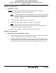
(3) Ensure that adequate attenuation rated for 406 MHz is installed between the ELT antenna
output and the measurement equipment to prevent damaging input circuitry, if required. At a
minimum, the attenuator should be rated at 30 dB, and 5 watts for a ½-second duration. As
shown in Figure 7. Performance Testing Equipment Setup.
Figure 7. Performance Testing Equipment Setup
SUBTASK 25-62-03-750-003
H. 121.5 MHz Frequency Measurement – Item 5a
(1) Connect the measuring device, referring to SUBTASK 25-62-03-750-002 on page 40.
(2) Activate the ELT by placing the control switch in the “ON” position.
(3) Wait three minutes.
(4) Perform SUBTASK 25-62-03-750-004 during the three-minute waiting period.
(5) Measure the frequency after the three-minute waiting period. The frequency should be within
tolerance specified in Table 3 on page 34.
NOTE
: If the 121.5 MHz carrier frequency is within specified tolerance, the 243.0 MHz
frequency will also be within tolerance.
SUBTASK 25-62-03-750-004
I. Audio Modulation Check – Item 5b
(1) Perform this check in conjunction with SUBTASK 25-62-03-750-003.
(2) Monitor 121.5 MHz on an AM receiver.
(3) Listen for the aural sweep tone on the receiver. The audio should “sound” like an ELT.
ELT ANTENNA
BNC CONNECTOR
(121.5/243.0 MHz)
TPS CONNECTOR
(406 MHz)
30 dB
ATTENUATOR
(if required)
MEASURING
DEVICE