
Owner's manual


25-62-03
Page 57 of 87
JUN 20/13
ACR ELECTRONICS, INC / ARTEX PRODUCTS
DESCRIPTION, OPERATION, INSTALLATION AND MAINTENANCE MANUAL
B406-4 (453-5004)
(2) Locate the mounting tray such that the ELT mounting frame cap has at least 5 inches (127
mm) of clearance for installation and removal.
(3) Mount the ELT as far aft as practical, but where it can be easily retrieved for maintenance.
NOTE
: Statistics show that the tail section of an airplane is likely to be less damaged during
a crash; therefore, providing a good mounting environment for the ELT.
(4) Additional installation guidance may be found in AC 43.13-2, Chapter 2, Paragraph 28, which
specifically addresses ELT installations.
SUBTASK 25-62-03-450-002
B. Installation
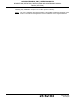
(1) See Figure 13. Typical Mounting Tray Installation.
Figure 13. Typical Mounting Tray Installation
(2) Install the necessary mounting structure as appropriate for the specific installation.
(3) Align the mounting tray (452-5050) on the mounting structure, such that the arrow on the
tray is within 10° of the longitudinal axis of the aircraft and pointing in the direction of flight.
(4) Mark the four holes needed for mounting the tray, using the tray as a pattern. The hole
pattern is also illustrated in Figure 12. B406-4 ELT Outline and Dimensions on page 56.
(5) Drill the four mounting holes with a #19 or 4.25 mm drill.
(6) Install the mounting tray with the 8-32 x 5/8” SS pan head phillips screws, flat washers, lock
washers, and nuts provided in the installation kit (455-7421), as shown in Figure 13. Typical
8-32 x 5/8 SCREW
(4 PLCS)
#8 FLAT WASHER
(4 PLCS)
#8 LOCK WASHER
(4 PLCS)
8-32 X 1/4 HEX NUT
(4 PLCS)
AIRFRAME
STRUCTURE (REF.)
EQUIPMENT MOUNTING
PLATE (REF.)
MOUNTING
TRAY