
Owner's manual


ACR ELECTRONICS, INC / ARTEX PRODUCTS
DESCRIPTION, OPERATION, INSTALLATION AND MAINTENANCE MANUAL
B406-4 (453-5004)
25-62-03
Page 72 of 87
JUN 20/13
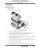
(11) Secure the mounting frame cap to the mounting tray with the thumbscrews and tighten them
to no more than 18 lb-in (203 N•cm).
(12) Tie up excess slack in the harness and coax cables, such that they form drip loops and there is
enough slack, approximately 5 in. (127 mm), to allow the mounting frame cap to be easily
pulled back.
NOTE
: Steps (1) through (11) are applicable any time the ELT has been removed and
undergoes reinstallation. Step (12) is only applicable at initial installation or if the
wiring and/or coax cables have been disturbed.
(13) Test the ELT installation in accordance with the requirements of SUBTASK 25-62-03-750-011
on page 45.
NOTE
: It is very important that the cockpit remote switch panel light illuminates immediately
upon ELT activation. If the light fails to illuminate immediately and stay on steady,
recheck the interface wiring and connections between the ELT and the remote switch
panel. The ELT local LED flashes every 3-4 seconds.
NOTE
: If verification of the digital message (i.e., 406 MHz Burst) is desired, follow the
procedures outlined in SUBTASK 25-62-03-750-009 on page 44.
SUBTASK 25-62-03-450-001
B. Harness ELT Receptacle Sealing
(1) Seal the harness receptacle at the ELT end to prevent moisture from penetrating the
connection, thus preventing water from beading up and causing bridging between connector
pins resulting in possible activation of the ELT. Use the following procedure:
NOTE
: Perform the sealing process once all tests have been satisfactorily completed and all
harness connections have been verified to be correct.
(a) Remove the mounting frame cap from the ELT.
(b) Unplug the receptacle from the ELT or pull the receptacle free of the mounting frame
cap, as applicable.
(c) Seal the back of the receptacle with GE RTV 162, or equivalent, such that moisture
cannot penetrate the backside of the receptacle around the terminal pins.
(d) Apply Dow Corning® 4 Electrical Insulating Compound, or an equivalent meeting MIL-S-
8660C, around the receptacle pins, such that the pin area is filled with compound.
(e) Plug the harness receptacle into the ELT.
(f) Wipe up excess sealing compound.
(g) Reinstall the mounting frame cap torquing the thumbscrews to no more than 18 lb-in.
(203 N•cm).