
User Manual


ACR ELECTRONICS, INC / ARTEX PRODUCTS
DESCRIPTION, OPERATION, INSTALLATION AND MAINTENANCE MANUAL
C406-N (453-5060), C406-N HM (453-5061)
25-62-13
Page 70 of 109
MAR 1/13
(5) Fabricate the following wires.
(a) Fabricate a ground wire long enough to reach from Pin 11 of the harness ELT plug to
aircraft ground.
NOTE
: This wire will be crimped in the same pin as the wire running from Pin 11 of the
ELT plug to the cockpit remote switch plug Pin 6, if the Pin 11 to Pin 6
connection is required. See Note 4 in "Figure 21. Remote Switch Harness
Wiring Diagram”, on page 69. Alternatively, the wires may be spliced in a
manner acceptable to the aircraft manufacturer, or as described in AC 43.13-1,
Paragraph 11-167.
(b) Fabricate a ground wire long enough to reach from Pin 9 of the remote switch plug to
aircraft ground.
(c) Fabricate a ground wire long enough to reach from the harness ELT plug strain relief to
aircraft ground.
(d) Fabricate a power wire long enough to reach from the remote switch plug (Pin 3) to a
+28 VDC battery power source.
(e) Fabricate a power wire long enough to reach from the ELT plug (Pin 10) to a +28 VDC
power source.
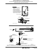
(f) Fabricate two wires of sufficient length to reach from the harness ELT plug to the
buzzer.
NOTE
: These wires provide power and ground for the buzzer. Use appropriate means
of identification for the wires, such that the wires can be readily identified.
(g) Prepare the wires as follows:
1
Strip approximately 0.15 in. (3 mm) of insulation from the remote switch wire ends
and 0.19 in. (5 mm) from the ELT wire ends.
2
Dress and tin the bare wires to prevent the strands from fraying during terminal
crimping operations.
(6) Crimp contact sockets (151-6657) on the harness wire ends at the ELT, as follows:
NOTE
: Use crimp tool M22520/7-01 and die M22570/7-06, or equivalent.
(a) The Pin 11 ground wire. The wire running from Pin 11 to remote switch Pin 6 is
terminated in the same pin, if this wire is required. See "Figure 21. Remote Switch
Harness Wiring Diagram”, on page 69. Make a note of the wire identification for later
reference.
(b) On each of the remaining wire ends at the harness ELT end.
(c) The +28 VDC switchable power source wire.
(d) The buzzer power and ground wires.
(e) On each of the twisted pair ARINC 429 input wires.
(7) Crimp appropriately sized ring terminals on the buzzer ends of the buzzer power and ground
wires.