DGL-1 (Dongle) Programming Adapter Description, Operation, Installation and Maintenance Manual This manual includes data for the equipment that follows: Component Part No. Model No. Emergency Locator Transmitter 453-6603 DGL-1 ACR ELECTRONICS, INC / ARTEX PRODUCTS 5757 Ravenswood Rd, Ft. Lauderdale, FL 33312 Cage Code: 18560 25-69-01 Page 1 of 44 JUN 27/12 570-4010 Rev.
ARTEX PRODUCTS / ACR ELECTRONICS, INC DESCRIPTION, OPERATION, INSTALLATION AND MAINTENANCE MANUAL DGL-1, DONGLE (453-4010) PROPRIETARY INFORMATION This document contains proprietary information and such information may not be disclosed to others for any purpose, nor used for manufacturing purposes without written permission from ACR Electronics. Information in this manual is subject to change without notice.
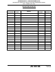
ARTEX PRODUCTS / ACR ELECTRONICS, INC DESCRIPTION, OPERATION, INSTALLATION AND MAINTENANCE MANUAL DGL-1, DONGLE (453-4010) RECORD OF REVISIONS REVISION CHANGE DATE - RELEASE Nov 06/2002 - DCN 2124 Dec 18/2002 - DCN 2147 Feb 17/2003 - DCN 2188 Apr 21/2003 - DCN 2369 Apr 21/2004 A DCN 3144 Dec 11/2007 B DCA W9612 MMM DD/YYYY C ECO 14756 Jul 28/2011 D ECO 15119 Jun 27/2012 REVISION CHANGE 25-69-01 DATE Page 3 of 44 JUN 27/12
ARTEX PRODUCTS / ACR ELECTRONICS, INC DESCRIPTION, OPERATION, INSTALLATION AND MAINTENANCE MANUAL DGL-1, DONGLE (453-4010) THIS IS A BLANK PAGE 25-69-01 Page 4 of 44 JUN 27/12
ARTEX PRODUCTS / ACR ELECTRONICS, INC DESCRIPTION, OPERATION, INSTALLATION AND MAINTENANCE MANUAL DGL-1, DONGLE (453-4010) SERVICE BULLETIN LIST SERVICE BULLETIN NO ISSUE DATE SUBJECT MANUAL REV NO 25-69-01 MANUAL REV DATE Page 5 of 44 JUN 27/12
ARTEX PRODUCTS / ACR ELECTRONICS, INC DESCRIPTION, OPERATION, INSTALLATION AND MAINTENANCE MANUAL DGL-1, DONGLE (453-4010) THIS IS A BLANK PAGE 25-69-01 Page 6 of 44 JUN 27/12
ARTEX PRODUCTS / ACR ELECTRONICS, INC DESCRIPTION, OPERATION, INSTALLATION AND MAINTENANCE MANUAL DGL-1, DONGLE (453-4010) LIST OF EFFECTIVE PAGES SUBJECT PAGE DATE SUBJECT PAGE DATE Title Page 1 Jun 27/12 Installation (cont.
ARTEX PRODUCTS / ACR ELECTRONICS, INC DESCRIPTION, OPERATION, INSTALLATION AND MAINTENANCE MANUAL DGL-1, DONGLE (453-4010) THIS IS A BLANK PAGE 25-69-01 Page 8 of 44 JUN 27/12
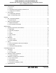
ARTEX PRODUCTS / ACR ELECTRONICS, INC DESCRIPTION, OPERATION, INSTALLATION AND MAINTENANCE MANUAL DGL-1, DONGLE (453-4010) TABLE OF CONTENTS RECORD OF REVISIONS . . . . . . . . . . . . . . . . . . . . . . . . . . . . . . . . . . . . . . . . . . . . . . . . . . . . . . . . . . . . 3 SERVICE BULLETIN LIST . . . . . . . . . . . . . . . . . . . . . . . . . . . . . . . . . . . . . . . . . . . . . . . . . . . . . . . . . . . 3 LIST OF EFFECTIVE PAGES . . . . . . . . . . . . . . . . . . . . . . . . . . . . . . .
ARTEX PRODUCTS / ACR ELECTRONICS, INC DESCRIPTION, OPERATION, INSTALLATION AND MAINTENANCE MANUAL DGL-1, DONGLE (453-4010) 3. Test Procedures . . . . . . . . . . . . . . . . . . . . . . . . . . . . . . . . . . . . . . . . . . . . . . . . . . . . . . . . . . 24 A. General . . . . . . . . . . . . . . . . . . . . . . . . . . . . . . . . . . . . . . . . . . . . . . . . . . . . . . . . . . . . . 24 B. 24-Bit Address Reprogramming Verification Test . . . . . . . . . . . . . . . . . . . . . . . . . . . . . . . .
ARTEX PRODUCTS / ACR ELECTRONICS, INC DESCRIPTION, OPERATION, INSTALLATION AND MAINTENANCE MANUAL DGL-1, DONGLE (453-4010) LIST OF FIGURES Figure 1. DGL-1 (Dongle) Programming Adapter with ELT Cover . . . . . . . . . . . . . . . . . . . . . . . . . . . . 14 Figure 2. DGL-1 (Dongle) Programming Adapter Assembly . . . . . . . . . . . . . . . . . . . . . . . . . . . . . . . . 19 Figure 3. Dongle Removal Sequence . . . . . . . . . . . . . . . . . . . . . . . . . . . . . . . . . . . . . . . . . . . . . . .
ARTEX PRODUCTS / ACR ELECTRONICS, INC DESCRIPTION, OPERATION, INSTALLATION AND MAINTENANCE MANUAL DGL-1, DONGLE (453-4010) 25-69-01 Page 12 of 44 JUN 27/12
ARTEX PRODUCTS / ACR ELECTRONICS, INC DESCRIPTION, OPERATION, INSTALLATION AND MAINTENANCE MANUAL DGL-1, DONGLE (453-4010) INTRODUCTION TASK 25-62-30-870-801 1. Manual Usage SUBTASK 25-62-30-990-001 A. General (1) This manual describes the operation, installation, and maintenance of the DGL-1 (Dongle) Programming Adapter. This information is provided to ensure initial and continued airworthiness. Information presented in this manual is accurate at time of printing, but is subject to change.
ARTEX PRODUCTS / ACR ELECTRONICS, INC DESCRIPTION, OPERATION, INSTALLATION AND MAINTENANCE MANUAL DGL-1, DONGLE (453-4010) configuration or a navigation interface, should be installed and maintained in accordance with the written instructions specific to the accessory. NOTE: (5) Contact ACR Electronics, Inc., for optional accessories approved for use with a ME406 Series ELT.
ARTEX PRODUCTS / ACR ELECTRONICS, INC DESCRIPTION, OPERATION, INSTALLATION AND MAINTENANCE MANUAL DGL-1, DONGLE (453-4010) TASK 25-62-30-990-805 4. List of Acronyms, Abbreviations, and Definitions SUBTASK 25-62-30-990-001 Term Definition AC Advisory Circular – A Federal Aviation Administration (USA) bulletin with special information. For the purposes of this document, the acronym AC does not refer to electrical alternating current.
ARTEX PRODUCTS / ACR ELECTRONICS, INC DESCRIPTION, OPERATION, INSTALLATION AND MAINTENANCE MANUAL DGL-1, DONGLE (453-4010) indicate a wire specification and MIL-STD-XXXX would indicate a standard). MSB Most Significant Bit - The bit position in a binary number having the greatest value. P/N Part Number – Refers to an ACR part number, unless otherwise noted. Part numbers are also indicated with parentheses (e.g., XXXXXXX).
ARTEX PRODUCTS / ACR ELECTRONICS, INC DESCRIPTION, OPERATION, INSTALLATION AND MAINTENANCE MANUAL DGL-1, DONGLE (453-4010) TASK 25-62-30-990-806 5. References SUBTASK 25-62-30-990-001 A. Regulatory Documents (1) The following regulatory documents are referred to herein. When referring to such documents, it is the manual user’s responsibility to ensure they are using the latest revision or release of such documents.
ARTEX PRODUCTS / ACR ELECTRONICS, INC DESCRIPTION, OPERATION, INSTALLATION AND MAINTENANCE MANUAL DGL-1, DONGLE (453-4010) THIS IS A BLANK PAGE 25-69-01 Page 18 of 44 JUN 27/12
ARTEX PRODUCTS / ACR ELECTRONICS, INC DESCRIPTION, OPERATION, INSTALLATION AND MAINTENANCE MANUAL DGL-1, DONGLE (453-4010) DESCRIPTION AND OPERATION TASK 25-62-30-870-801 1. Description SUBTASK 25-69-01-870-001 A. Functional Overview (1) The Dongle is connected to an ELT to allow the operator to easily program aircraft 24-bit address (Standard Location Protocol) into a compatible ELT.
ARTEX PRODUCTS / ACR ELECTRONICS, INC DESCRIPTION, OPERATION, INSTALLATION AND MAINTENANCE MANUAL DGL-1, DONGLE (453-4010) SUBTASK 25-69-01-870-003 C. 24-Bit Address Reprogramming Functionality CAUTION: THE PROGRAMMING AND LABELING OF THE ELT MUST MATCH THE AIRCRAFT IN WHICH IT IS INSTALLED. REMARK THE ELT PRODUCT LABEL AS NECESSARY TO REFLECT NEW PROGRAMMING AND/OR COUNTRY OR REGISTRY.
ARTEX PRODUCTS / ACR ELECTRONICS, INC DESCRIPTION, OPERATION, INSTALLATION AND MAINTENANCE MANUAL DGL-1, DONGLE (453-4010) TASK 25-69-01-870-802 2. Operation SUBTASK 25-69-01-870-001 A. Operational Overview (1) Operation of the Dongle is automatic and requires no operator interface other than activating the +28 VDC power source and verifying no failure mode is present. See “Fault Isolation” on page 26.
ARTEX PRODUCTS / ACR ELECTRONICS, INC DESCRIPTION, OPERATION, INSTALLATION AND MAINTENANCE MANUAL DGL-1, DONGLE (453-4010) TASK 25-69-01-870-803 3. Specifications SUBTASK 25-69-01-870-001 A. Electrical (1) Table 1 lists the electrical specifications of the Dongle. Table 1. Electrical Specifications CRITERIA PARAMETER CHARACTERISTIC Pin 1 RX Input TTL Pin 2 TX Output TTL Pin 3 5.6 VDC Output 5.6 VDC ±0.
ARTEX PRODUCTS / ACR ELECTRONICS, INC DESCRIPTION, OPERATION, INSTALLATION AND MAINTENANCE MANUAL DGL-1, DONGLE (453-4010) TEST AND FAULT ISOLATION TASK 25-69-01-750-801 1. General SUBTASK 25-69-01-990-001 A. Applicability (1) This section only covers inspection, testing, and fault isolation procedures specific to the Dongle.
ARTEX PRODUCTS / ACR ELECTRONICS, INC DESCRIPTION, OPERATION, INSTALLATION AND MAINTENANCE MANUAL DGL-1, DONGLE (453-4010) TASK 25-69-01-750-801 3. Test Procedures SUBTASK 25-69-01-990-001 A. General CAUTION: (1) ANY ELT RUNNING V133 SOFTWARE (SEE PRODUCT LABEL) MUST BE TESTED IN AN RF CONTAINER, SCREEN ROOM, OR CONNECTED TO A DUMMY LOAD VIA THE ANTENNA COAX CONNECTION, BECAUSE THE V133 SOFTWARE TRANSMITS A FIXED TEST MESSAGE AT ELT RESET, NECESSITATING A “LIVE” BROADCAST TO READ THE ACTUAL MESSAGE.
ARTEX PRODUCTS / ACR ELECTRONICS, INC DESCRIPTION, OPERATION, INSTALLATION AND MAINTENANCE MANUAL DGL-1, DONGLE (453-4010) (8) Verify the 24-bit address has changed as a result of changing the position of the MSB DIP switch. (9) Repeat Steps 3 through 8 to return and verify the original configuration of the Dongle. SUBTASK 25-69-01-750-001 C.
ARTEX PRODUCTS / ACR ELECTRONICS, INC DESCRIPTION, OPERATION, INSTALLATION AND MAINTENANCE MANUAL DGL-1, DONGLE (453-4010) TASK 25-69-01-810-801 4. Fault Isolation SUBTASK 25-69-01-810-801 A. Troubleshooting Guidelines (1) "Table 3. Troubleshooting Guide" provides the Dongle troubleshooting guidelines for installation and operational issues. Table 3.
ARTEX PRODUCTS / ACR ELECTRONICS, INC DESCRIPTION, OPERATION, INSTALLATION AND MAINTENANCE MANUAL DGL-1, DONGLE (453-4010) REMOVAL TASK 25-69-01-010-801 1. DGL-1 Programming Adapter SUBTASK 25-69-01-010-001 A. Dongle Removal (1) See "Figure 3. Dongle Removal Sequence". DONGLE SCREW (TYP. OF 8) GASKET COVER COVER ASSEMBLY Figure 3. Dongle Removal Sequence (2) Remove black circular connector from the Dongle. (3) Remove the screws attaching the mounting plate to the top cover assembly.
ARTEX PRODUCTS / ACR ELECTRONICS, INC DESCRIPTION, OPERATION, INSTALLATION AND MAINTENANCE MANUAL DGL-1, DONGLE (453-4010) TASK 25-69-01-500-801 2. Material or Equipment Return SUBTASK 25-69-01-510-001 A.
ARTEX PRODUCTS / ACR ELECTRONICS, INC DESCRIPTION, OPERATION, INSTALLATION AND MAINTENANCE MANUAL DGL-1, DONGLE (453-4010) INSTALLATION TASK 25-69-01-450-801 1. Regulatory Requirements and Guidelines SUBTASK 25-69-01-990-001 A. Applicability (1) The regulatory requirements and guidelines for ELT installations discussed in the following subtasks are applicable to installation of the DGL-1 Dongle Programming Adapter and must be applied to the DGL-1 Dongle Programming Adapter.
ARTEX PRODUCTS / ACR ELECTRONICS, INC DESCRIPTION, OPERATION, INSTALLATION AND MAINTENANCE MANUAL DGL-1, DONGLE (453-4010) SUBTASK 25-69-01-990-006 F. RTCA (1) (2) DO-204, § 3.1.8 guidelines for mounting a ELT: (a) The ELT shall be mounted to primary aircraft load carrying structures, such as trusses, bulkheads, longerons, spars, or floor beams. (b) The mounts shall have a maximum static local deflection no greater than 0.1 inches (2.
ARTEX PRODUCTS / ACR ELECTRONICS, INC DESCRIPTION, OPERATION, INSTALLATION AND MAINTENANCE MANUAL DGL-1, DONGLE (453-4010) TASK 25-69-01-410-802 2. Mechanical SUBTASK 25-69-01-450-001 A. Dongle Location CAUTION: AVOID LOCATION THE DONGLE WHERE IT MAY BE SUBJECTED TO UNPROTECTED EXPOSURE TO HARSH CHEMICAL FLUIDS, SUCH AS DEICING COMPONDS. THESE TYPES OF CHECMICALS MAY CAUSE DAMAGE TO FASTENERS AND ELECTRICAL COMPONENTS, AS WELL AS ELECTRICAL CONNECTOR CORROSION.
ARTEX PRODUCTS / ACR ELECTRONICS, INC DESCRIPTION, OPERATION, INSTALLATION AND MAINTENANCE MANUAL DGL-1, DONGLE (453-4010) TASK 25-69-01-450-805 3. Wiring SUBTASK 25-69-01-990-001 A. General Considerations and Recommendations CAUTION: IF GROUND OR OTHER CONNECTIONS ARE BROKEN OR OTHERWISE DAMAGED, THE ELT IS STILL CAPABLE OF AUTOMATIC ACTIVATION; HOWEVER, THE COCKPIT REMOTE SWITCH MAY BE INCAPABLE OF RESETTING THE ELT AND OPERATION MAY NOT BE INDICATED ON THE REMOTE SWITCH LED.
ARTEX PRODUCTS / ACR ELECTRONICS, INC DESCRIPTION, OPERATION, INSTALLATION AND MAINTENANCE MANUAL DGL-1, DONGLE (453-4010) SUBTASK 25-69-01-450-002 B. Dongle Wiring (1) Refer to "Figure 8. Dongle Wiring Diagram", on page 36. (2) Refer to the applicable ELT abbriviated component maintenance manual for pin configuation and additional wiring infromation. TO ANTENNA (TYP.) TO REMOTE SWITCH Figure 5.
ARTEX PRODUCTS / ACR ELECTRONICS, INC DESCRIPTION, OPERATION, INSTALLATION AND MAINTENANCE MANUAL DGL-1, DONGLE (453-4010) 3 6 2 9 5 1 12 8 11 4 7 10 Figure 6. Molex 12-Pin Connector Harness Arrangement (4) Assemble the wire harness with the Dongle wire harness (P/N 611-4010). See "Figure 8. Dongle Wiring Diagram", on page 36. NOTE: (5) Remote switch pin numbers are for an ARTEX standard remote switch (P/N 3456196-04).
ARTEX PRODUCTS / ACR ELECTRONICS, INC DESCRIPTION, OPERATION, INSTALLATION AND MAINTENANCE MANUAL DGL-1, DONGLE (453-4010) RED TO 28 VDC BLACK TO GROUND Figure 7. Molex Power and Ground Wires (9) Connect the ground to the black, un-terminated wire. NOTE: Refer to Raychem for specific instructions on the splice use. Alternate splices may be used if installed in accordance with FAA AC 43.13.1A, Section 445, Splices in Electrical Wire.
ARTEX PRODUCTS / ACR ELECTRONICS, INC DESCRIPTION, OPERATION, INSTALLATION AND MAINTENANCE MANUAL DGL-1, DONGLE (453-4010) ELT TX 12 1 TX RX 9 2 RX 5.6 V 10 3 5.6 V GND 11 5 GND HRN + 2 HRN + HRN – 4 HRN – G-SWT LOOP 5 G-SWT LOOP 8 LED 1 LED RST-1 3 RST-1 RST-2 6 RST-2 EXT ON 7 EXT ON 28 V 4 0.5 A DONGLE GND 6 HORN GND REMOTE SWITCH Figure 8.
ARTEX PRODUCTS / ACR ELECTRONICS, INC DESCRIPTION, OPERATION, INSTALLATION AND MAINTENANCE MANUAL DGL-1, DONGLE (453-4010) SUBTASK 25-69-01-450-002 24-Bit Address Reprogramming (1) The 24-bit address is composed of binary “1s” and “0s”, with a “1” electrically grounded to the airframe and “0” electrically open. (2) Encoding is accomplished by using a 24-bit address switch block which internally grounds selected addresses. (3) Remove the Dongle in accordance with “Dongle Removal” on page 27.
ARTEX PRODUCTS / ACR ELECTRONICS, INC DESCRIPTION, OPERATION, INSTALLATION AND MAINTENANCE MANUAL DGL-1, DONGLE (453-4010) 1 0 MSB LSB Figure 10. 24-Bit Address Switch Block (7) Test the installation in accordance with “24-Bit Address Reprogramming Verification Test” on page 24.
ARTEX PRODUCTS / ACR ELECTRONICS, INC DESCRIPTION, OPERATION, INSTALLATION AND MAINTENANCE MANUAL DGL-1, DONGLE (453-4010) ILLUSTRATED PARTS LIST TASK 25-69-01-990-801 1. Introduction SUBTASK 25-69-01-990-001 A. Purpose (1) This illustrated parts list (IPL) illustrates and lists the spare parts, with attaching hardware, applicable to the ME406 Series ELT.
ARTEX PRODUCTS / ACR ELECTRONICS, INC DESCRIPTION, OPERATION, INSTALLATION AND MAINTENANCE MANUAL DGL-1, DONGLE (453-4010) TASK 25-69-01-990-802 2. Manufacturer Name and Address SUBTASK 25-69-01-990-001 A. Ordering Information (1) Approved parts may be ordered from ACR Electronics, Inc. or any authorized dealer.
ARTEX PRODUCTS / ACR ELECTRONICS, INC DESCRIPTION, OPERATION, INSTALLATION AND MAINTENANCE MANUAL DGL-1, DONGLE (453-4010) TASK 25-69-01-990-803 3. Explanation of Detailed Parts List Entries SUBTASK 25-69-01-990-001 A. Fig # & Item Column (1) The first number at the top of the column is the figure number of the corresponding illustration. (2) The right hand number is the item number in the associated figure. (3) A dash (–) in front of an item means the part is not illustrated.
ARTEX PRODUCTS / ACR ELECTRONICS, INC DESCRIPTION, OPERATION, INSTALLATION AND MAINTENANCE MANUAL DGL-1, DONGLE (453-4010) (3) Assemblies, subassemblies, and detail parts subject to modification, deletion, addition, or replacement by an issued service bulletin, are annotated to indicate both pre- and postservice bulletin configurations.
ARTEX PRODUCTS / ACR ELECTRONICS, INC DESCRIPTION, OPERATION, INSTALLATION AND MAINTENANCE MANUAL DGL-1, DONGLE (453-4010) TASK 25-69-01-990-804 4. Detailed Parts List Figure 11. DGL-1 (Dongle) Programming Adapter Assembly 02 03 04 01 05 FIG # ITEM PART # 1234 NOMENCLATURE UPA 11 01 453-6603 Progamming Adapter Assembly, DGL-1, Dongle 1 02 453-6604 DGL-1 Dongle Main Assembly 1 ATTACHING PARTS 03 183-0050 . Plate, Mounting, ELT 1 04 201-6324-01 .
ARTEX PRODUCTS / ACR ELECTRONICS, INC DESCRIPTION, OPERATION, INSTALLATION AND MAINTENANCE MANUAL DGL-1, DONGLE (453-4010) Figure 12. Wire Harness 01 FIG # ITEM PART # 12 01 345-6196-04 1234 NOMENCLATURE Harness, DGL-1, Dongle UPA 1 ATTACHING PARTS – 455-4010-01 Install Kit, DGL-1 1 – 151-6627 Terminal, Crimp Male .062” Dia. 6 – 591-0999 Label, Hex Code 1 – 591-0429-01 Label, Country and Country Code 1 – 5610-1744-01 Soldersleeve Wire Splice .10 in.