ELT/NAV INTERFACE Description, Operation, Installation and Maintenance Manual This manual includes data for the equipment that follows: Component Part No. Model No. ELT/NAV Interface 453-6500 N/A ARTEX PRODUCTS / ACR ELECTRONICS, INC. 5757 Ravenswood Rd, Ft. Lauderdale, FL 33312 Cage Code: 60253 25-69-10 Page 1 of 58 APR 30/12 570-4602 Rev.
ARTEX PRODUCTS / ACR ELECTRONICS, INC. DESCRIPTION, OPERATION, INSTALLATION AND MAINTENANCE MANUAL 453-6500 PROPRIETARY INFORMATION This document contains proprietary information and such information may not be disclosed to others for any purpose, nor used for manufacturing purposes without written permission from ACR Electronics. Information in this manual is subject to change without notice. ACR Electronics, Inc.
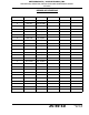
ARTEX PRODUCTS / ACR ELECTRONICS, INC. DESCRIPTION, OPERATION, INSTALLATION AND MAINTENANCE MANUAL 453-6500 RECORD OF REVISIONS REV NO. DCN NO.
ARTEX PRODUCTS / ACR ELECTRONICS, INC.
ARTEX PRODUCTS / ACR ELECTRONICS, INC.
ARTEX PRODUCTS / ACR ELECTRONICS, INC.
ARTEX PRODUCTS / ACR ELECTRONICS, INC.
ARTEX PRODUCTS / ACR ELECTRONICS, INC.
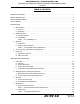
ARTEX PRODUCTS / ACR ELECTRONICS, INC. DESCRIPTION, OPERATION, INSTALLATION AND MAINTENANCE MANUAL 453-6500 TABLE OF CONTENTS RECORD OF REVISIONS . . . . . . . . . . . . . . . . . . . . . . . . . . . . . . . . . . . . . . . . . . . . . . . . . . . . . . . . . . . . 3 SERVICE BULLETIN LIST. . . . . . . . . . . . . . . . . . . . . . . . . . . . . . . . . . . . . . . . . . . . . . . . . . . . . . . . . . . . 5 LIST OF EFFECTIVE PAGES . . . . . . . . . . . . . . . . . . . . . . . . . . . . . . . . . . . . . .
ARTEX PRODUCTS / ACR ELECTRONICS, INC. DESCRIPTION, OPERATION, INSTALLATION AND MAINTENANCE MANUAL 453-6500 C. Electrical . . . . . . . . . . . . . . . . . . . . . . . . . . . . . . . . . . . . . . . . . . . . . . . . . . . . . . . . . . . . 30 Table 5. Electrical Specifications . . . . . . . . . . . . . . . . . . . . . . . . . . . . . . . . . . . . . . . . . . . 30 TEST AND FAULT ISOLATION 1. General . . . . . . . . . . . . . . . . . . . . . . . . . . . . . . . . . . . . . . . . . . . . . . . . . . . . . .
ARTEX PRODUCTS / ACR ELECTRONICS, INC. DESCRIPTION, OPERATION, INSTALLATION AND MAINTENANCE MANUAL 453-6500 ILLUSTRATED PARTS LIST 1. Introduction . . . . . . . . . . . . . . . . . . . . . . . . . . . . . . . . . . . . . . . . . . . . . . . . . . . . . . . . . . . . . 53 A. Purpose . . . . . . . . . . . . . . . . . . . . . . . . . . . . . . . . . . . . . . . . . . . . . . . . . . . . . . . . . . . . . 53 B. IPL Usage Guide . . . . . . . . . . . . . . . . . . . . . . . . . . . . . . . . . . . . . . . . . . .
ARTEX PRODUCTS / ACR ELECTRONICS, INC.
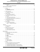
ARTEX PRODUCTS / ACR ELECTRONICS, INC. DESCRIPTION, OPERATION, INSTALLATION AND MAINTENANCE MANUAL 453-6500 LIST OF FIGURES Figure 1. ELT/NAV Interface System Integration . . . . . . . . . . . . . . . . . . . . . . . . . . . . . . . . . . . . . . . . 23 Figure 2. ELT/NAV Interface Isometric View . . . . . . . . . . . . . . . . . . . . . . . . . . . . . . . . . . . . . . . . . . . 24 Figure 3. Examples of Location Protocol 406 MHz Messages . . . . . . . . . . . . . . . . . . . . . . . . . . . . . . . .
ARTEX PRODUCTS / ACR ELECTRONICS, INC.
ARTEX PRODUCTS / ACR ELECTRONICS, INC. DESCRIPTION, OPERATION, INSTALLATION AND MAINTENANCE MANUAL 453-6500 INTRODUCTION TASK 25-69-10-990-801 1. Manual Usage SUBTASK 25-69-10-990-001 A. General (1) This manual describes the operation, installation, and maintenance of the ELT/NAV Interface. This information is provided to ensure initial and continued airworthiness. Information presented in this manual is accurate at time of printing, but is subject to change.
ARTEX PRODUCTS / ACR ELECTRONICS, INC. DESCRIPTION, OPERATION, INSTALLATION AND MAINTENANCE MANUAL 453-6500 TASK 25-69-10-990-802 2. Model Description SUBTASK 25-69-10-990-001 A. ELT/NAV Interface (1) The ELT/NAV Interface provides the means to transmit position data received from the aircraft navigation system to the ELT. (2) The ELT/NAV Interface is available in two installation configurations: (a) 24-bit auto reprogramming and position data, or (b) Position data only.
ARTEX PRODUCTS / ACR ELECTRONICS, INC. DESCRIPTION, OPERATION, INSTALLATION AND MAINTENANCE MANUAL 453-6500 TASK 25-69-10-990-803 3. Approvals SUBTASK 25-69-10-990-001 A. Certification (1) FAA TSO C126 System Component NOTE: (a) (2) Details of TSO certification for the ELT/NAV Interface are available in the “TSO Qualification Test Report for the ELT/NAV Interface System” (Document 6288). The conditions and tests required for TSO approval of this article are minimum performance standards.
ARTEX PRODUCTS / ACR ELECTRONICS, INC. DESCRIPTION, OPERATION, INSTALLATION AND MAINTENANCE MANUAL 453-6500 CATEGORY SECTION DESCRIPTION X 15.0 Magnetic Effect B 16.0 Power Input A 17.0 Voltage Spike B 18.0 Audio Frequency Susceptibility A 19.0 Induced Signal Susceptibility 204 20.0 Radio Frequency Susceptibility B 21.0 Emission of Radio Frequency Energy X 22.0 Lightning X 23.0 Lightning Direct Effects X 24.
ARTEX PRODUCTS / ACR ELECTRONICS, INC. DESCRIPTION, OPERATION, INSTALLATION AND MAINTENANCE MANUAL 453-6500 TASK 25-69-10-990-804 4. List of Acronyms, Abbreviations, and Definitions SUBTASK 25-69-10-990-001 Term Definition AC Advisory Circular – A Federal Aviation Administration (USA) bulletin with special information. For the purposes of this document, the acronym AC does not refer to electrical alternating current. AWG American Wire Gauge – An electrical wire diameter standard.
ARTEX PRODUCTS / ACR ELECTRONICS, INC. DESCRIPTION, OPERATION, INSTALLATION AND MAINTENANCE MANUAL 453-6500 FAR Federal Aviation Regulations – The rules and regulations governing the manufacture, certification, operation, maintenance, repair, and alteration of aircraft in the United States. FORM 337 FAA Form 337 is required anytime a major repair and/or major alteration is performed on an aircraft.
ARTEX PRODUCTS / ACR ELECTRONICS, INC. DESCRIPTION, OPERATION, INSTALLATION AND MAINTENANCE MANUAL 453-6500 TASK 25-69-10-990-805 5. References SUBTASK 25-69-10-990-001 A. Regulatory Documents (1) The following regulatory documents are referred to herein. When referring to such documents, it is the manual user’s responsibility to ensure they are using the latest revision or release of such documents.
ARTEX PRODUCTS / ACR ELECTRONICS, INC. DESCRIPTION, OPERATION, INSTALLATION AND MAINTENANCE MANUAL 453-6500 (c) DO-182, “Emergency Locator Transmitter (ELT) Equipment Installation and Performance” (d) DO-183, “Minimal Operational Performance Standards for Emergency Locator Transmitters - Automatic Fixed-ELT (AF), Automatic Portable-ELT (AP), Automatic Deployable-ELT (AD), Survival-ELT (S) Operating on 121.5 and 243.
ARTEX PRODUCTS / ACR ELECTRONICS, INC. DESCRIPTION, OPERATION, INSTALLATION AND MAINTENANCE MANUAL 453-6500 DESCRIPTION AND OPERATION TASK 25-69-10-870-801 1. Description SUBTASK 25-69-10-870-001 A. Overview (1) The ELT/NAV Interface is integrated into the ELT system. See "Figure 1. ELT/NAV Interface System Integration". PROTECTIVE TOP COVER (REF.) ELT/NAV INTERFACE TO ANTENNA (REF.) ELT (REF.) REMOTE SWITCH (REF.) MOUNTING TRAY (REF.
ARTEX PRODUCTS / ACR ELECTRONICS, INC. DESCRIPTION, OPERATION, INSTALLATION AND MAINTENANCE MANUAL 453-6500 SUBTASK 25-69-10-870-002 B. Physical Description (1) The ELT/NAV Interface components are housed in a 0.125 inch (3.2 mm) thick aluminum chassis; finished with a chromate conversion primer and a safety orange, high solids epoxy or polyurethane finish. See "Figure 2. ELT/NAV Interface Isometric View". Figure 2. ELT/NAV Interface Isometric View SUBTASK 25-69-10-870-003 C.
ARTEX PRODUCTS / ACR ELECTRONICS, INC. DESCRIPTION, OPERATION, INSTALLATION AND MAINTENANCE MANUAL 453-6500 SUBTASK 25-69-10-870-004 D. 24-Bit Address Reprogramming Functionality CAUTION: THE PROGRAMMING AND LABELING OF THE ELT MUST MATCH THE AIRCRAFT IN WHICH IT IS INSTALLED. REMARK THE ELT PRODUCT LABEL AS NECESSARY TO REFLECT NEW PROGRAMMING AND/OR COUNTRY OF REGISTRY.
ARTEX PRODUCTS / ACR ELECTRONICS, INC. DESCRIPTION, OPERATION, INSTALLATION AND MAINTENANCE MANUAL 453-6500 TASK 25-69-10-870-802 2. Navigation System Interface Requirements SUBTASK 25-69-10-870-001 A. ARINC 429 Latitude and Longitude Data Input (1) The ELT/NAV Interface will accept signals “A” and “B” from any ARINC 429 navigation system. (2) The interface looks for labels “310” (latitude) and “311” (longitude), which contain position data.
ARTEX PRODUCTS / ACR ELECTRONICS, INC. DESCRIPTION, OPERATION, INSTALLATION AND MAINTENANCE MANUAL 453-6500 TASK 25-69-10-870-803 3. Operation SUBTASK 25-69-10-870-001 A. Position Data Processing (1) Operation of ELT/NAV Interface position data processing (i.e., receive, convert, and transmit) is automatic and requires no operator interface other than activating the +28 VDC power source.
ARTEX PRODUCTS / ACR ELECTRONICS, INC. DESCRIPTION, OPERATION, INSTALLATION AND MAINTENANCE MANUAL 453-6500 TASK 25-69-10-870-804 4. Specifications SUBTASK 25-69-10-870-001 A. Physical and Environmental (1) Table 3 lists the ELT/NAV Interface physical and environmental specifications. Table 3.
ARTEX PRODUCTS / ACR ELECTRONICS, INC. DESCRIPTION, OPERATION, INSTALLATION AND MAINTENANCE MANUAL 453-6500 SUBTASK 25-69-10-870-002 B. Input/Output (1) Table 4 lists the ELT/NAV Interface input/output specifications. Table 4. Input/Output Specifications PIN DESCRIPTION CHARACTERISTIC P2-1 Power Input +28 VDC ±5 VDC 300 mA max. P2-2 5.6 VDC Output Vmax = 6.0 VDC Vmin = 5.
ARTEX PRODUCTS / ACR ELECTRONICS, INC. DESCRIPTION, OPERATION, INSTALLATION AND MAINTENANCE MANUAL 453-6500 SUBTASK 25-69-10-870-003 C. Electrical (1) Table 5 lists the ELT/NAV Interface electrical specifications. Table 5.
ARTEX PRODUCTS / ACR ELECTRONICS, INC. DESCRIPTION, OPERATION, INSTALLATION AND MAINTENANCE MANUAL 453-6500 TEST AND FAULT ISOLATION TASK 25-69-10-750-801 1. General SUBTASK 25-69-10-990-001 A. Applicability (1) This section only covers inspection, testing, and fault isolation procedures specific to the ELT/ NAV Interface.
ARTEX PRODUCTS / ACR ELECTRONICS, INC. DESCRIPTION, OPERATION, INSTALLATION AND MAINTENANCE MANUAL 453-6500 TASK 25-69-10-750-802 2. Periodic Inspection SUBTASK 25-69-10-220-001 A. Inspection Procedures (1) Remove the ELT/NAV Interface in accordance with SUBTASK 25-69-10-050-001, on page 39. (2) Perform a visual inspection of the chassis exterior, checking for: (a) Damage to the finish, (b) Corrosion, (c) Excessive wear of the mounting holes, and (d) Cracks in the mounting flanges.
ARTEX PRODUCTS / ACR ELECTRONICS, INC. DESCRIPTION, OPERATION, INSTALLATION AND MAINTENANCE MANUAL 453-6500 TASK 25-69-10-750-803 3. Periodic Testing SUBTASK 25-69-10-750-001 A. Position Data ELT Self-Test (1) This is a recommended periodic test. (2) The following test procedure incorporates the steps necessary to confirm operation of the ELT/NAV Interface into the “Installed Transmitter Test” procedure defined in the applicable ELT abbreviated component maintenance manual.
ARTEX PRODUCTS / ACR ELECTRONICS, INC. DESCRIPTION, OPERATION, INSTALLATION AND MAINTENANCE MANUAL 453-6500 TASK 25-69-10-750-804 4. Post-Installation Functional Testing SUBTASK 25-69-10-990-001 A.
ARTEX PRODUCTS / ACR ELECTRONICS, INC. DESCRIPTION, OPERATION, INSTALLATION AND MAINTENANCE MANUAL 453-6500 (f) Allow the ELT to transmit for approximately 5 seconds. (g) Deactivate the ELT and read the test message broadcast at “turn off”. NOTE: (2) The test message broadcast by the ELT at “turn-off” contains all the information in an actual distress message, except there is a special digital prefix that informs COSPAS-SARSAT satellites to ignore the message. Message examples are shown in "Figure 3.
ARTEX PRODUCTS / ACR ELECTRONICS, INC. DESCRIPTION, OPERATION, INSTALLATION AND MAINTENANCE MANUAL 453-6500 SUBTASK 25-69-10-750-002 C. 24-Bit Address Reprogramming Verification Test This test procedure verifies the ELT/NAV Interface has updated the aircraft 24-bit address ID in the ELT programming. (1) Apply power to the ELT/NAV Interface, while the ELT remains off (i.e, inactive). Reprogramming takes place within 30 seconds of power up. (2) Monitor the ELT for the next 2 minutes.
ARTEX PRODUCTS / ACR ELECTRONICS, INC. DESCRIPTION, OPERATION, INSTALLATION AND MAINTENANCE MANUAL 453-6500 TASK 25-69-10-750-805 5. Post-Reprogramming Check SUBTASK 25-69-10-750-001 A. 15-Digit Hex ID Verification (1) 15-digit hex ID verification should be performed any time an ELT is installed in an aircraft to verify the ELT is properly labeled and registered. (2) Perform the following procedure within the first 5 minutes after the hour (UTC), as required by AC 43.
ARTEX PRODUCTS / ACR ELECTRONICS, INC. DESCRIPTION, OPERATION, INSTALLATION AND MAINTENANCE MANUAL 453-6500 TASK 25-69-10-810-801 6. Fault Isolation SUBTASK 25-69-10-810-001 A. Troubleshooting Guidelines (1) Table 6 provides ELT troubleshooting guidelines for installation and operational issues. Table 6.
ARTEX PRODUCTS / ACR ELECTRONICS, INC. DESCRIPTION, OPERATION, INSTALLATION AND MAINTENANCE MANUAL 453-6500 REMOVAL TASK 25-69-10-050-801 1. ELT/NAV Interface SUBTASK 25-69-10-050-001 A. Removal (1) See "Figure 5. ELT/NAV Interface Removal". (2) Disconnect ELT/NAV Interface plugs: (a) P2, and (b) P1, if installed. (3) Install connector covers to protect the ELT/NAV Interface receptacles. (4) Remove the screws attaching the ELT/NAV interface to the mounting structure. ELT (REF.
ARTEX PRODUCTS / ACR ELECTRONICS, INC. DESCRIPTION, OPERATION, INSTALLATION AND MAINTENANCE MANUAL 453-6500 TASK 25-69-10-500-801 2. Material or Equipment Return SUBTASK 25-69-10-510-001 A. Shipment Information (1) If any material or equipment is to be returned to the factory, under warranty or otherwise, ACR Electronics, Inc.
ARTEX PRODUCTS / ACR ELECTRONICS, INC. DESCRIPTION, OPERATION, INSTALLATION AND MAINTENANCE MANUAL 453-6500 INSTALLATION TASK 25-69-10-450-801 1. Regulatory Requirements and Guidelines SUBTASK 25-69-10-990-001 A. Applicability (1) The regulatory requirements and guidelines for ELT installations discussed in the following subtasks are applicable to installation of the ELT/NAV Interface and must be applied to the ELT/NAV Interface.
ARTEX PRODUCTS / ACR ELECTRONICS, INC. DESCRIPTION, OPERATION, INSTALLATION AND MAINTENANCE MANUAL 453-6500 SUBTASK 25-69-10-990-006 F. RTCA (1) (2) DO-204, § 3.1.8 guidelines for mounting a ELT: (a) The ELT shall be mounted to primary aircraft load carrying structures, such as trusses, bulkheads, longerons, spars, or floor beams. (b) The mounts shall have a maximum static local deflection no greater than 0.1 inches (2.
ARTEX PRODUCTS / ACR ELECTRONICS, INC. DESCRIPTION, OPERATION, INSTALLATION AND MAINTENANCE MANUAL 453-6500 TASK 25-69-10-450-802 2. Mechanical SUBTASK 25-69-10-450-001 A. Chassis Location CAUTION: AVOID LOCATING THE ELT/NAV INTERFACE WHERE IT MAY BE SUBJECTED TO UNPROTECTED EXPOSURE TO HARSH CHEMICAL FLUIDS, SUCH AS DEICING COMPOUNDS. THESE TYPES OF CHEMICALS MAY CAUSE DAMAGE TO FASTENERS AND ELECTRICAL COMPONENTS, AS WELL AS ELECTRICAL CONNECTOR CORROSION.
ARTEX PRODUCTS / ACR ELECTRONICS, INC. DESCRIPTION, OPERATION, INSTALLATION AND MAINTENANCE MANUAL 453-6500 (3) Align the ELT/NAV Interface on the mounting structure. (4) Mark the six holes needed for mounting, using the unit as a pattern. Hole pattern dimensions are also illustrated in "Figure 6. ELT/NAV Interface Outline and Dimensions”, on page 43. (5) Drill the six mounting holes with a #19 or 4.25 mm drill.
ARTEX PRODUCTS / ACR ELECTRONICS, INC. DESCRIPTION, OPERATION, INSTALLATION AND MAINTENANCE MANUAL 453-6500 TASK 25-69-10-450-803 3. Wiring SUBTASK 25-69-10-990-001 A. General Considerations and Recommendations CAUTION: IF GROUND OR OTHER CONNECTIONS ARE BROKEN OR OTHERWISE DAMAGED, THE ELT IS STILL CAPABLE OF AUTOMATIC ACTIVATION; HOWEVER, ELT/NAV INTERFACE OPERATION MAY BE AFFECTED AND POSITION DATA MAY NOT BE TRANSMITTED TO THE ELT.
ARTEX PRODUCTS / ACR ELECTRONICS, INC. DESCRIPTION, OPERATION, INSTALLATION AND MAINTENANCE MANUAL 453-6500 SUBTASK 25-69-10-450-001 ELT and Navigation System Interfaces CAUTION: (1) DO NOT CONNECT THE ELT/NAV INTERFACE POWER WIRE DIRECTLY TO THE BATTERY. THE UNIT DRAWS POWER WHENEVER POWER IS APPLIED TO IT AND COULD DRAIN THE AIRCRAFT BATTERY WHEN NOT IN USE. See "Figure 8. ELT/NAV Interface Wiring Diagram".
ARTEX PRODUCTS / ACR ELECTRONICS, INC. DESCRIPTION, OPERATION, INSTALLATION AND MAINTENANCE MANUAL 453-6500 (4) Fabricate a ground wire of sufficient length to reach from the ELT/NAV Interface to a suitable aircraft ground location. (a) Strip approximately 0.19 in. (5 mm) of insulation from each end of each of the ground wire. (b) Dress and tin the bare wire ends to prevent the strands from fraying during terminal crimping operations.
ARTEX PRODUCTS / ACR ELECTRONICS, INC. DESCRIPTION, OPERATION, INSTALLATION AND MAINTENANCE MANUAL 453-6500 (11) Feed the interface wires at the ELT/NAV Interface end through the 183-6503 strain relief. See "Figure 10. ELT/NAV Interface Wiring Installation". P1 #18 31-PIN PLUG CONTACT PINS #18 STRAIN RELIEF P2 #16 24-PIN PLUG CONTACT SOCKETS #16 STRAIN RELIEF Figure 10.
ARTEX PRODUCTS / ACR ELECTRONICS, INC. DESCRIPTION, OPERATION, INSTALLATION AND MAINTENANCE MANUAL 453-6500 (18) Connect the P2 plug to the ELT/NAV Interface. (19) Install the 150-6504 protective cap on the ELT/NAV Interface P1 plug, if the 24-bit address reprogramming option is not used. (20) Test the installation in accordance with the procedure outlined in SUBTASK 25-69-10-750-001, on page 34.
ARTEX PRODUCTS / ACR ELECTRONICS, INC. DESCRIPTION, OPERATION, INSTALLATION AND MAINTENANCE MANUAL 453-6500 (b) Dress and tin the bare wire ends to prevent the strands from fraying during terminal crimping operations. (5) Crimp contact pins 151-2101 onto one end of each wire. (6) Insert the contact pins into the appropriate pin locations of the 150-6502 plug (P1). See "Figure 8. ELT/NAV Interface Wiring Diagram”, on page 46.
ARTEX PRODUCTS / ACR ELECTRONICS, INC. DESCRIPTION, OPERATION, INSTALLATION AND MAINTENANCE MANUAL 453-6500 (9) Connect the other end of each wire to the switch block in accordance with the switch block manufacturer’s written instructions. (10) Verify the wiring P1 plug pin locations and block switch positions are correct based on the applicable 24-bit address. See "Figure 8. ELT/NAV Interface Wiring Diagram”, on page 46.
ARTEX PRODUCTS / ACR ELECTRONICS, INC.
ARTEX PRODUCTS / ACR ELECTRONICS, INC. DESCRIPTION, OPERATION, INSTALLATION AND MAINTENANCE MANUAL 453-6500 ILLUSTRATED PARTS LIST TASK 25-69-10-990-801 1. Introduction SUBTASK 25-69-10-990-001 A. Purpose (1) This illustrated parts list (IPL) illustrates and lists the spare parts, with attaching hardware, applicable to the ELT/NAV Interface.
ARTEX PRODUCTS / ACR ELECTRONICS, INC. DESCRIPTION, OPERATION, INSTALLATION AND MAINTENANCE MANUAL 453-6500 TASK 25-69-10-990-802 2. Manufacturer Name and Address SUBTASK 25-69-10-990-001 A. Ordering Information (1) Approved parts may be ordered from ACR Electronics, or any authorized dealer. CONTACT INFORMATION Sales, Artex Products / ACR Electronics, Inc.
ARTEX PRODUCTS / ACR ELECTRONICS, INC. DESCRIPTION, OPERATION, INSTALLATION AND MAINTENANCE MANUAL 453-6500 TASK 25-69-10-990-803 3. Explanation of Detailed Parts List Entries SUBTASK 25-69-10-990-001 A. Fig # & Item Column (1) The first number at the top of the column is the figure number of the corresponding illustration. (2) The right hand number is the item number in the associated figure. (3) A dash (–) in front of an item means the part is not illustrated.
ARTEX PRODUCTS / ACR ELECTRONICS, INC. DESCRIPTION, OPERATION, INSTALLATION AND MAINTENANCE MANUAL 453-6500 (3) Assemblies, subassemblies, and detail parts subject to modification, deletion, addition, or replacement by an issued service bulletin, are annotated to indicate both pre- and postservice bulletin configurations.
ARTEX PRODUCTS / ACR ELECTRONICS, INC. DESCRIPTION, OPERATION, INSTALLATION AND MAINTENANCE MANUAL 453-6500 TASK 25-69-10-990-804 4. Detailed Parts List Figure 12.
ARTEX PRODUCTS / ACR ELECTRONICS, INC. DESCRIPTION, OPERATION, INSTALLATION AND MAINTENANCE MANUAL 453-6500 Figure 13. Electrical Components 04 05 ELT/NAV INTERFACE (REF.) 01 02 06 03 FIG # ITEM PART # 13 01 150-6503 1234 NOMENCLATURE Connector, #16 Circular (24-Position) UPA 1 *** 02 151-2100 . Contact, Socket #20 26 03 183-6503 Strain Relief, #16 1 *** 04 150-6502 Connector, #18 Circular (31-Position) 1 *** 05 151-2101 .