
Owner manual


25-62-21
Page 71 of 86
JUL 31/12
ACR ELECTRONICS, INC / ARTEX PRODUCTS
DESCRIPTION, OPERATION, INSTALLATION AND MAINTENANCE MANUAL
G406-4 (453-5012)
TASK 25-62-21-410-802
7. ELT Installation
SUBTASK 25-62-21-410-001
A. Installation and Test
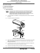
(1) See "Figure 21. ELT Installation Sequence".
Figure 21. ELT Installation Sequence
(2) Verify the ELT local switch is in the “OFF” position.
(3) Insert the ELT into the mounting tray at an angle, such that the locking ears at the end
opposite the direction-of-flight arrow fit into the mounting tray locking slots.
(4) Press the ELT down until it is fully seated in the mounting tray.
(5) Install the protective top cover assembly (452-0224) on the ELT by fitting the cover locking
slots over the locking ears on the ELT.
(6) Push the cover toward the connector end of the ELT and seat it down in place on the ELT.
(7) Route the antenna coax cables through the appropriate mounting frame cap access holes.
(8) Connect the antenna coax cables to the ELT.
(9) Connect the 12-pin harness receptacle to the ELT.
(10) Slide the mounting frame cap into place over the mounting tray and protective top cover.
PROTECTIVE TOP
COVER ASSY
MOUNTING FRAME
CAP ASSY
ELT MAIN
ASSY
MOUNTING
TRAY ASSY
CONNECT COAX
CABLE
CONNECT HARNESS
1
TIGHTEN THUMBSCREW
(2 PLCS)
Tighten to no more than
18 lb-in (203 Ncm)
2
3
5
6
7
NOTE: Coax cables and
wiring harness not
shown for clarity.
CONNECT COAX
CABLE
4