
Owner manual


25-62-21
Page 75 of 86
JUL 31/12
ACR ELECTRONICS, INC / ARTEX PRODUCTS
DESCRIPTION, OPERATION, INSTALLATION AND MAINTENANCE MANUAL
G406-4 (453-5012)
(7) Reset the ELT by toggling the ELT local control switch to “ON” and back to “OFF” after 1-2
seconds.
NOTE
: This step is necessary because the ELT will occasionally activate when power is
connected to it in Step 6.
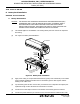
(8) Fit the battery pack into place on the ELT, while dressing the wires away from the standoffs to
avoid pinching the wires between the standoffs and battery pack.
(9) Turn the battery pack bottom face up to facilitate installing the screws, while securely holding
the ELT and battery pack together.
(10) Install the four battery pack retaining screws about half way (i.e., leave them loose).
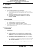
(11) Tighten and torque the screws as shown in "Figure 23. Battery Pack Retaining Screw
Tightening Pattern". Torque to 6-8 lb-in (68-90 N•cm).
Figure 23. Battery Pack Retaining Screw Tightening Pattern
(12) Perform an ELT self-test as follows:
(a) Set the ELT local control switch in the “ON” position. The LED will begin flashing every 3-
4 seconds.
(b) Return the switch to the “OFF” position after 1-2 seconds. If the ELT is working properly,
the LED will stay on for approximately 1 second and then flash the following expected
error codes, which should be ignored.
1
1-flash and 3-flash errors, which are generated because the ELT is not installed
and connected to an antenna, etc.
2
A 5-flash error will be indicated if the ELT is programed with a location protocol,
and is generated because the ELT is not connected to the navigation system and
receiving position data.
(c) If a 7-flash error code is indicated, there is a problem with the battery or battery
connection wiring. Refer to Table 6, on page 48.
SWITCH/CONNECTOR
END
1
2
3
4