DESCRIPTION, INSTALLATION, OPERATION AND MAINTENANCE MANUAL REMOTE SWITCH 453-0023, MODULE INTERFACE 453-1101 AND BUZZER 452-6505 INSTALLATION 570-0023 Rev. G Artex Products / ACR Electronics, Inc. Artex Products / ACR Electronics, Inc. 5757 Ravenswood Road, Fort Lauderdale, Florida USA Phone 954-981-3333, Fax 954-983-5087 www.acrartex.
Artex Products / ACR Electronics, Inc. 570-0023 Rev. G Notices 1. This document discloses subject matter in which ACR Electronics, Inc. has proprietary rights. Neither receipt nor possession thereof confers or transfers any right to reproduce or disclose the document, any part thereof, any information therein, or any physical article or device, or practice any method or process except by written permission from or written agreement with ACR Electronics, Inc. 2.
Artex Products / ACR Electronics, Inc. 570-0023 Rev.
Artex Products / ACR Electronics, Inc. 570-0023 Rev.
Artex Products / ACR Electronics, Inc. 570-0023 Rev.
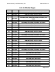
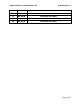
Artex Products / ACR Electronics, Inc. 570-0023 Rev. G Table of Contents 1. INTRODUCTION ................................................................................................8 2. PARTS LIST .......................................................................................................8 3. WIRING PIN OUT .............................................................................................9 4. HARNESS .........................................................................
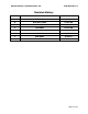
Artex Products / ACR Electronics, Inc. 570-0023 Rev. G List of Figures Figure 1: Wiring Diagram for Shielded Cable (Composite Aircraft) ........................................................ 11 Figure 2: Wiring Diagram for Unshielded Telephone Cable ................................................................... 11 Figure 3: Wiring Diagram for Shielded Cable (Metal Aircraft) ................................................................
Artex Products / ACR Electronics, Inc. 1. 570-0023 Rev. G INTRODUCTION This manual contains detailed information to install the self-powered remote switch 453-0023, module interface 453-1101, and the buzzer 452-6505. In addition, these instructions highlight the methodology to replace the cell in the remote switch. This manual is not intended to be an installation for the ELT system. Use this manual in conjunction with any of Artex ME406 series ELT manuals. 2.
Artex Products / ACR Electronics, Inc. 3. 570-0023 Rev. G WIRING PIN OUT The following information highlights the pin out of the remote switch and module interface.
Artex Products / ACR Electronics, Inc. 4. 570-0023 Rev. G HARNESS Due to the large array of configurations possible, ACR Electronics, Inc. does not provide a harness or RJ11 plugs (telephone connector) as part of the installation of the ELT. Accordingly, it is the responsibility of the installer to manufacture a harness or ensure that the existing harness is adequate for the installation. The harness must be manufactured following the cross-wired configuration mentioned in Subsection 6.2.
Artex Products / ACR Electronics, Inc. 5. 570-0023 Rev. G WIRING DIAGRAMS Refer to the following wiring diagrams to connect the remote switch 453-0023, module interface 453-1101, and buzzer 452-6505 to the ME406 series ELT. NOTE: For Ameri-King or ACK ELT retrofit application, refer to Subsection 6.1. Figures 1 and 2 apply to composite aircraft, whereas Figures 3 and 4 apply to metal aircraft.
Artex Products / ACR Electronics, Inc. 570-0023 Rev. G Figures 3 and 4 apply to metal aircraft.
Artex Products / ACR Electronics, Inc. 6. 453-0023 REMOTE SWITCH INSTALLATION 6.1 Ameri-King and ACK Installation Retrofit 570-0023 Rev. G Ameri-King retrofit: The remote switch 453-0023 and ME406 series ELT cannot be used in conjunction with the Ameri-King interconnecting cable unless extender 611-0018 is connected directly with the Ameri-King cable. This 611-0018 extender is provided as part of the ELT installation pack list or can be ordered as line item.
Artex Products / ACR Electronics, Inc. 570-0023 Rev. G ACK retrofit: The remote switch 453-0023 and ME406 series ELT cannot be used in conjunction with the ACK interconnecting cable unless Flat Cable 611-0019 is connected directly with the ACK cable. This 611-0019 cable is provided as part of the ELT installation pack list or can be ordered as line item. The cable is installed on the ELT side. The 611-0018 extender can be discarded since it intended for Ameri-King ELT retrofit.
Artex Products / ACR Electronics, Inc. 570-0023 Rev. G 6.2 Typical Installation 6.2.1 Due to the large array of configurations possible, ACR Electronics, Inc. does not provide a harness or RJ11 plugs (telephone connector) as part of the installation of the ELT. 6.2.2 The harness must be manufactured following the cross-wired configuration shown below. NOTE: Refer to Subsection 6.1 for ACK and Ameri-King retrofits.
Artex Products / ACR Electronics, Inc. 570-0023 Rev. G 6.3 Panel Cutout Instructions 6.3.1 Select a mounting location where the remote switch can be seen from the pilot’s seated location, easily be reached by the pilot, out of direct sunlight, and can accommodate the remote switch and the label. Depending on the remote switch orientation on the control panel, choose the appropriate label and discard the other one. Label 591-0003 and label 591-3029 are provided in the 455-0023 pack list.
Artex Products / ACR Electronics, Inc. 570-0023 Rev. G 6.3.3 Clean the application surface area thoroughly prior to applying label 591-0003 or 5913029. 6.3.4 Remove the paper backing from the label and line up the label over the cutout. 6.3.5 Press firmly and evenly over the label to produce maximum adhesion. 6.3.6 Trim the label with an Exacto knife if it partially covers the mounting holes.
Artex Products / ACR Electronics, Inc. 570-0023 Rev. G 7. INSTALLATION 7.1 Instructions 7.1.1 Feed the modular jack connector from the harness through the panel cutout. 7.1.2 Plug the modular jack connector to the remote switch. Figure 7: Harness to Remote Switch Connection 7.1.3 Slide the remote switch and the harness inside the cutout following the orientation shown below. 7.1.4 Secure the remote switch using the hardware provided in the 455-0023 pack list.
Artex Products / ACR Electronics, Inc. 7.1.5 570-0023 Rev. G Fasten the ground wire along the harness within one inch of the remote switch using a tie cable. NOTE: The ground wire should have enough slack to prevent tensile load. Figure 9: Remote switch wire tensile load release (Panel not shown) 7.1.6 Connect the remote switch 26 AWG ground wire according to the wiring diagrams highlighted in section 5 using a ring or a fork terminal quick disconnect.
Artex Products / ACR Electronics, Inc. 570-0023 Rev. G 8. 453-1101 MODULE INTERFACE INSTALLATION 8.1 Instructions 8.1.1 Place the two sealing strips 850-0814 provided in the 455-7420 install kit into the ELT 15-pin D-sub connector. 8.1.2 Insert the module interface 453-1101 into the ELT D-sub and secure it in place using the two thumbscrews. The torque on the thumbscrews is 4 to 5 Lb-in.
Artex Products / ACR Electronics, Inc. 570-0023 Rev. G 9. 453-1101 MODULE INTERFACE AND 452-6505 BUZZER WIRING 9.1 Instructions 9.1.1 Follow the appropriate wiring diagram in Section 5, depending if the aircraft is metal or composite. Connect RED wire to Horn Power connection Connect BLACK wire to A/C Ground Cap & stow BLUE wire 9.1.2 Mount the buzzer according to the instructions highlighted in the ME406 series ELT manuals.
Artex Products / ACR Electronics, Inc. 570-0023 Rev. G 10.2 Mating Cover Removal 10.2.1 Remove the four retaining nuts and screws securing the remote switch 453-0023 to the panel. 10.2.2 Slide the remote switch from the panel. 10.2.3 Cut the tie cables securing the ground wire to the harness. 10.2.4 Disconnect the modular jack connector of the harness from the remote switch. 10.2.5 Remove the four retaining screws from the remote switch to access the cell compartment. 10.2.
Artex Products / ACR Electronics, Inc. 570-0023 Rev. G 10.3.2 Carefully remove the cell 131-0001 from the plastic cell holder and keep the conical spring. Spring Figure 12: Conical Spring 10.3.3 Dispose of the cell according to the instructions specified in section 10.6. 10.3.4 Carefully slide the replacement cell 131-0001 inside the plastic cell holder following the polarity mentioned inside the holder and on the cell, or by matching the positive (+) end of the cell to the red wire side of the holder.
Artex Products / ACR Electronics, Inc. 570-0023 Rev. G 10.3.7 Gently route the black and red wires from the plastic cell holder away from the leads of the rocker switch if necessary.
Artex Products / ACR Electronics, Inc. 570-0023 Rev. G 10.3.8 Position the ground wire (black) along the side of the plastic cell holder and away from the screw boss. Black Wire Screw boss Figure 15: Ground Wire 10.3.9 Refer to Subsection 10.5 to install the mating cover.
Artex Products / ACR Electronics, Inc. 570-0023 Rev. G 10.4 Cell Replacement from Cell Holder with Built-in Spring 10.4.1 Carefully remove the cell 131-0001 from the plastic cell holder. 10.4.2 Dispose of the cell according to the instructions specified in Subsection 10.6. 10.4.
Artex Products / ACR Electronics, Inc. 570-0023 Rev. G 10.4.5 Release the spring and ensure that it is properly pushing against the end of the cell. Figure 18: Spring Fit 10.4.6 Gently route the black and red wires from the plastic cell holder away from the leads of the rocker switch if necessary.
Artex Products / ACR Electronics, Inc. 570-0023 Rev. G 10.4.7 Position the ground wire (black) along the side of the plastic cell holder and away from the screw boss.
Artex Products / ACR Electronics, Inc. 570-0023 Rev. G 10.5 Mating Cover Installation 10.5.1 Install the mating cover to the assembly by matching the cutouts according to the different components. 10.5.2 Ensure that the 26 AWG ground wire is properly fed through the notch of the mating cover and is not pinched by the screw boss. Mating cover Figure 21: Mating Cover Installation 10.5.3 Secure the covers together using the retaining screws previously removed. The torque on the screws is 2.
Artex Products / ACR Electronics, Inc. 570-0023 Rev. G 10.6 Cell Disposal Instructions Lithium batteries are best disposed of as a non-hazardous waste when fully or mostly discharged. The Federal Environmental Protection Agency (EPA) governed by the Resource Conservation and Recovery Act (RCRA) do not list or exempt Lithium as a hazardous waste.
Artex Products / ACR Electronics, Inc. 12. 570-0023 Rev. G SPECIFICATIONS 12.1 Components Dimensions The following dimensions are displayed in [millimeters] and inches. Figure 23: 453-0023 Remote Switch Figure 24: 453-1101 Module Interface 12.2 Components Weight PART NUMBER DESCRIPTION WEIGHT 452-6505 Buzzer, Piezo .34 oz (9.64 gr.) Max. 453-0023 Remote Switch, Self-Powered 1.30 oz (36.85 gr.) Max. 453-1101 Module Interface, ELT to Remote Switch 1 oz (28.35 gr.) Max.
Artex Products / ACR Electronics, Inc. 570-0023 Rev. G 12.3 Environmental Categories DO-160D Environmental categories for nameplates: Remote switch 453-0023: DO-160D Env. Cat. F1XCAA[204]XWXXXXXXXXA[XXX]X[XXXX]XXX Module interface 453-1101: DO-160D Env.
Artex Products / ACR Electronics, Inc. 13. 570-0023 Rev. G INDEX 4 455-0023 Pack List, 8 455-7420 Pack List, 8 5 591-0003 Label, 16 591-3029 Label, 16 6 611-0018 Extender, 13 611-0019 Cable, 14 L Label 591-0003, 16 Label 591-0036, 19, 29 Label 591-3029, 16 LED, 18, 30 List of Figures, 7 M Module Interface Installation, 20, 21 O Orientation, Remote Switch, 18, 19 A ACK retrofit, 14 Advisory Circular 43.