
User guide


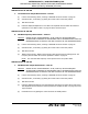


Table Of Contents
- Record of Revisions
- Service Bulletin List
- List of Effective Pages
- Table of Contents
- List of Figures
- Introduction
- Description and Operation
- Test and Fault Isolation
- 1. Inspection and Test Regulatory Requirements
- 2. Inspection and Test Procedures
- A. Checklist
- B. Preparation
- C. Coax Cable and Wiring Connections Inspection – Item 1
- D. Mounting Tray and Hardware Inspection – Item 2
- E. Battery Pack Inspection – Item 3
- F. G-Switch Functional Check – Item 4
- G. Performance Testing Setup
- H. 121.5 MHz Frequency Measurement – Item 5a
- I. Audio Modulation Check – Item 5b
- J. 121.5 MHz Power Output Measurement – Item 5c
- K. 406 MHz Frequency Measurement – Item 5d
- L. 406 MHz Power Output Measurement – Item 5e
- M. Current Draw Test – Item 5f
- N. Digital Message Verification – Item 5g
- O. ELT Reset Check – Item 5h
- P. Installed Transmitter Test – Item 6
- Q. Antenna Test – Item 7
- R. Inspection and Test Documentation – Item 8
- 3. Fault Isolation
- Removal
- Installation
- 1. Regulatory Requirements and Guidelines
- 2. Mounting Tray
- 3. Antenna
- 4. Remote Switch
- 5. Buzzer
- 6. Wiring
- A. General Considerations and Recommendations
- B. Remote Switch Harness Fabrication
- C. ELT D-Sub Plug Installation
- D. Cockpit Remote Switch 9-Pin Plug Installation
- E. Wiring Installation
- F. Antenna Connection
- G. Cockpit Remote Switch Power Connection
- H. Remote Switch Alternate Power Source
- I. Airframe Ground Connections
- J. Buzzer Connections
- K. Remote Switch Final Installation
- 7. ELT Installation
- 8. Battery Pack Installation
- 9. Helicopter Installations - Special Considerations
- Appendix A – ELT Registration
- Illustrated Parts List

ARTEX PRODUCTS / ACR ELECTRONICS, INC
DESCRIPTION, OPERATION, INSTALLATION AND MAINTENANCE MANUAL
ME406 (453-6603), ME406HM (453-6604)
25-62-30
Page 36 of 84
Jun 25/13
concurrently and test equipment settings to be quickly switched from one test to another.
By doing so, the three-minute warm-up requirement can be eliminated from a number of
tests and battery run time minimized to a large extent.
(1) Place the ELT in a container or screen room capable of substantially attenuating RF signals, or
the transmitter power output shall be connected to a suitable dummy load to minimize
radiation.
(2) Use the ELT’s own battery pack as the power source for these measurements. An alternate
power source can be used where lengthy servicing, other than the performance tests, is
anticipated.
(3) Ensure that adequate attenuation rated for 406 MHz is installed between the ELT antenna
output and the measurement equipment to prevent damaging input circuitry, if required. At a
minimum, the attenuator should be rated at 30 dB, and 5 watts for a ½-second duration. As
shown in Figure 8 Performance Testing Equipment Setup.
Figure 8 Performance Testing Equipment Setup
SUBTASK 25-62-30-750-003
H. 121.5 MHz Frequency Measurement – Item 5a
(1) Connect the measuring device, referring to SUBTASK 25-62-30-750-002 on page 35.
(2) Activate the ELT by placing the control switch in the “ON” position.
(3) Wait three minutes.
(4) Perform SUBTASK 25-62-30-750-004 during the three-minute waiting period.
(5) Measure the frequency after the three-minute waiting period. The frequency must be within
the tolerance specified in Table 3 on page 29.
SUBTASK 25-62-30-750-004
I. Audio Modulation Check – Item 5b
(1) Perform this check in conjunction with SUBTASK 25-62-30-750-003.
(2) Monitor 121.5 MHz on an AM receiver.
(3) Listen for the aural sweep tone on the receiver. The audio should “sound” like an ELT.
ELT ANTENNA
BNC CONNECTOR
30 dB
ATTENUATOR
(if required)
MEASURING
DEVICE