
User guide


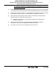


Table Of Contents
- Record of Revisions
- Service Bulletin List
- List of Effective Pages
- Table of Contents
- List of Figures
- Introduction
- Description and Operation
- Test and Fault Isolation
- 1. Inspection and Test Regulatory Requirements
- 2. Inspection and Test Procedures
- A. Checklist
- B. Preparation
- C. Coax Cable and Wiring Connections Inspection – Item 1
- D. Mounting Tray and Hardware Inspection – Item 2
- E. Battery Pack Inspection – Item 3
- F. G-Switch Functional Check – Item 4
- G. Performance Testing Setup
- H. 121.5 MHz Frequency Measurement – Item 5a
- I. Audio Modulation Check – Item 5b
- J. 121.5 MHz Power Output Measurement – Item 5c
- K. 406 MHz Frequency Measurement – Item 5d
- L. 406 MHz Power Output Measurement – Item 5e
- M. Current Draw Test – Item 5f
- N. Digital Message Verification – Item 5g
- O. ELT Reset Check – Item 5h
- P. Installed Transmitter Test – Item 6
- Q. Antenna Test – Item 7
- R. Inspection and Test Documentation – Item 8
- 3. Fault Isolation
- Removal
- Installation
- 1. Regulatory Requirements and Guidelines
- 2. Mounting Tray
- 3. Antenna
- 4. Remote Switch
- 5. Buzzer
- 6. Wiring
- A. General Considerations and Recommendations
- B. Remote Switch Harness Fabrication
- C. ELT D-Sub Plug Installation
- D. Cockpit Remote Switch 9-Pin Plug Installation
- E. Wiring Installation
- F. Antenna Connection
- G. Cockpit Remote Switch Power Connection
- H. Remote Switch Alternate Power Source
- I. Airframe Ground Connections
- J. Buzzer Connections
- K. Remote Switch Final Installation
- 7. ELT Installation
- 8. Battery Pack Installation
- 9. Helicopter Installations - Special Considerations
- Appendix A – ELT Registration
- Illustrated Parts List

ARTEX PRODUCTS / ACR ELECTRONICS, INC
DESCRIPTION, OPERATION, INSTALLATION AND MAINTENANCE MANUAL
ME406 (453-6603), ME406HM (453-6604)
25-62-30
Page 52 of 84
Jun 25/13
SUBTASK 25-62-30-450-002
B. Installation
(1) See Figure 14 Typical Mounting Tray Installation.
Figure 14 Typical Mounting Tray Installation
(2) Install the necessary mounting structure as appropriate for the specific installation.
(3) Align the mounting tray (452-3034) on the mounting structure, such that the arrow on the
tray is within 10° of the longitudinal axis of the aircraft and pointing in the direction of flight.
NOTE
: Refer to TASK 25-62-30-410-803 on page 74 for guidelines on ELT orientation in a
helicopter.
(4) Mark the four holes needed for mounting the tray, using the tray as a pattern. The hole
pattern is also illustrated in Figure 13 ME406 Series ELT Outline and Dimensions on page 51.
(5) Drill the four mounting holes with a #19 or 4.25 mm drill.
(6) Install the mounting tray with the hardware supplied in the installation kit (455-7423), as
shown in Figure 14 Typical Mounting Tray Installation on page 52.
NOTE
: The use of substitute mounting hardware is acceptable provided the hardware used
meets or exceeds the strength and corrosion resistance of the original hardware.
(a) Torque to 12 ±1 lb-in (136 ± 11 N•cm).
8-32 x 5/8 SCREW
(4 PLCS)
#8 FLAT WASHER
(4 PLCS)
NOTE: LOCKWASHER OR
LOCKNUT RECOMMENDED
8-32 X 1/4 HEX NUT
(4 PLCS)
AIRFRAME
STRUCTURE (REF.)
EQUIPMENT MOUNTING
PLATE (REF.)
MOUNTING
TRAY
NOTE: LOCKWASHER OR
LOCKNUT RECOMMENDED
8-32 X 1/4 HEX NUT
(4 PLCS)
MOUNTING
TRAY
AIRFRAME
STRUCTURE (REF.)
EQUIPMENT MOUNTING
PLATE (REF.)
8-32 x 5/8 SCREW
(4 PLCS)
#8 FLAT WASHER
(4 PLCS)