
User guide


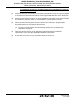


Table Of Contents
- Record of Revisions
- Service Bulletin List
- List of Effective Pages
- Table of Contents
- List of Figures
- Introduction
- Description and Operation
- Test and Fault Isolation
- 1. Inspection and Test Regulatory Requirements
- 2. Inspection and Test Procedures
- A. Checklist
- B. Preparation
- C. Coax Cable and Wiring Connections Inspection – Item 1
- D. Mounting Tray and Hardware Inspection – Item 2
- E. Battery Pack Inspection – Item 3
- F. G-Switch Functional Check – Item 4
- G. Performance Testing Setup
- H. 121.5 MHz Frequency Measurement – Item 5a
- I. Audio Modulation Check – Item 5b
- J. 121.5 MHz Power Output Measurement – Item 5c
- K. 406 MHz Frequency Measurement – Item 5d
- L. 406 MHz Power Output Measurement – Item 5e
- M. Current Draw Test – Item 5f
- N. Digital Message Verification – Item 5g
- O. ELT Reset Check – Item 5h
- P. Installed Transmitter Test – Item 6
- Q. Antenna Test – Item 7
- R. Inspection and Test Documentation – Item 8
- 3. Fault Isolation
- Removal
- Installation
- 1. Regulatory Requirements and Guidelines
- 2. Mounting Tray
- 3. Antenna
- 4. Remote Switch
- 5. Buzzer
- 6. Wiring
- A. General Considerations and Recommendations
- B. Remote Switch Harness Fabrication
- C. ELT D-Sub Plug Installation
- D. Cockpit Remote Switch 9-Pin Plug Installation
- E. Wiring Installation
- F. Antenna Connection
- G. Cockpit Remote Switch Power Connection
- H. Remote Switch Alternate Power Source
- I. Airframe Ground Connections
- J. Buzzer Connections
- K. Remote Switch Final Installation
- 7. ELT Installation
- 8. Battery Pack Installation
- 9. Helicopter Installations - Special Considerations
- Appendix A – ELT Registration
- Illustrated Parts List

25-62-30
Page 57 of 84
Jun 25/13
ARTEX PRODUCTS / ACR ELECTRONICS, INC
DESCRIPTION, OPERATION, INSTALLATION AND MAINTENANCE MANUAL
ME406 (453-6603), ME406HM (453-6604)
TASK 25-62-30-450-804
5. Buzzer
SUBTASK 25-62-30-450-001
A. Location
CAUTION
: PLACING THE BUZZER IN THE COCKPIT IS NOT RECOMMENDED DUE TO THE
POTENTIAL FOR DISTRACTION. THE BUZZER PRODUCES A LOUD, SIREN-TYPE
SOUND WHEN THE ELT IS ACTIVATED. SINCE THE BUZZER OPERATES IN TANDEM
WITH THE COCKPIT LED, IT WOULD ONLY SERVE AS A REDUNDANT WARNING
INDICATOR IN THE COCKPIT.
(1) Select a suitable location for the buzzer.
NOTE
: The buzzer may be located anywhere in the aircraft; however, the recommended
location is near the ELT, as the buzzer is loud enough to be heard outside the aircraft
when the engine(s) is not running. When the engine(s) is running, the LED on the
cockpit remote switch assembly will warn the pilot the ELT is active.
SUBTASK 25-62-30-450-002
B. Installation
(1) Fabricate a bracket suitable for supporting the buzzer. See Figure 17 Buzzer Outline and
Dimensions.
NOTE
: Refer to the aircraft manufacturer’s written instructions or AC 43.13-2, as applicable,
for approved bracket fabrication and installation methods.
Figure 17 Buzzer Outline and Dimensions
(2) Attach the bracket to the airframe such that the buzzer is adequately supported and does not
show any significant evidence of distorting the airframe skin.
(3) Install the buzzer in the bracket.
(a) Remove the panel mounting nut and insert the buzzer in the bracket.
NOTE
: Alternatively, the buzzer may be attached to the support using the mounting
holes on the buzzer body and appropriate hardware.
(b) Install the panel mounting nut and tighten it securely.
1.56 (40)
1.32 (34)
Ø 1.10 (28)
2X Ø 0.12 (3)
0.70
(18)
1.00
(25)
0.16 (4)
452-6505
Dimensions in inches (mm)