
User guide


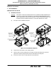


Table Of Contents
- Record of Revisions
- Service Bulletin List
- List of Effective Pages
- Table of Contents
- List of Figures
- Introduction
- Description and Operation
- Test and Fault Isolation
- 1. Inspection and Test Regulatory Requirements
- 2. Inspection and Test Procedures
- A. Checklist
- B. Preparation
- C. Coax Cable and Wiring Connections Inspection – Item 1
- D. Mounting Tray and Hardware Inspection – Item 2
- E. Battery Pack Inspection – Item 3
- F. G-Switch Functional Check – Item 4
- G. Performance Testing Setup
- H. 121.5 MHz Frequency Measurement – Item 5a
- I. Audio Modulation Check – Item 5b
- J. 121.5 MHz Power Output Measurement – Item 5c
- K. 406 MHz Frequency Measurement – Item 5d
- L. 406 MHz Power Output Measurement – Item 5e
- M. Current Draw Test – Item 5f
- N. Digital Message Verification – Item 5g
- O. ELT Reset Check – Item 5h
- P. Installed Transmitter Test – Item 6
- Q. Antenna Test – Item 7
- R. Inspection and Test Documentation – Item 8
- 3. Fault Isolation
- Removal
- Installation
- 1. Regulatory Requirements and Guidelines
- 2. Mounting Tray
- 3. Antenna
- 4. Remote Switch
- 5. Buzzer
- 6. Wiring
- A. General Considerations and Recommendations
- B. Remote Switch Harness Fabrication
- C. ELT D-Sub Plug Installation
- D. Cockpit Remote Switch 9-Pin Plug Installation
- E. Wiring Installation
- F. Antenna Connection
- G. Cockpit Remote Switch Power Connection
- H. Remote Switch Alternate Power Source
- I. Airframe Ground Connections
- J. Buzzer Connections
- K. Remote Switch Final Installation
- 7. ELT Installation
- 8. Battery Pack Installation
- 9. Helicopter Installations - Special Considerations
- Appendix A – ELT Registration
- Illustrated Parts List

25-62-30
Page 61 of 84
Jun 25/13
ARTEX PRODUCTS / ACR ELECTRONICS, INC
DESCRIPTION, OPERATION, INSTALLATION AND MAINTENANCE MANUAL
ME406 (453-6603), ME406HM (453-6604)
SUBTASK 25-62-30-450-001
B. Remote Switch Harness Fabrication
(1) See Figure 20 Remote Switch Harness Arrangement.
Figure 20 Remote Switch Harness Arrangement
(2) Fabricate a harness long enough to reach from the ELT to the cockpit remote switch, allowing
enough slack to provide a drip loop at the ELT end and a service loop at the cockpit remote
switch end. Refer to the appropriate wiring diagram.
(a) Strip approximately 0.15 in. (3 mm) of insulation from the remote switch end of each of
the harness cable wires.
(b) Dress and tin the bare wires to prevent the strands from fraying during terminal
crimping operations.
(3) Fabricate ground wires as required, based on the wiring diagram appropriate for the
installation.
(4) Fabricate a power wire long enough to reach from the remote switch plug (Pin 1 or Pin 3) to
the selected aircraft power source.
(5) Prepare the wires fabricated in Steps (3) and (4), as described in Steps (2)(a) and (2)(b).
(6) Fabricate two wires, one of sufficient length to reach from the ELT D-Sub connector plug to
the buzzer and the other from the buzzer to ground.
NOTE
: These wires provide power and ground for the buzzer. Use appropriate means of
identification for the wires, such that the wires can be readily identified.
PIN 1
PIN 7
PIN 9
PIN 3
151-5009
USE FEMALE
CRIMP PINS
(151-6628)
REMOTE SWITCH (REF.)
REMOTE SWITCH
HARNESS
PIN 1
PIN 9
PIN 8
PIN 15
150-1130
ME406 ELT (REF.)
NOTE: D-SUB HOUSING
NOT SHOWN FOR CLARITY