
User guide


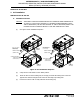


Table Of Contents
- Record of Revisions
- Service Bulletin List
- List of Effective Pages
- Table of Contents
- List of Figures
- Introduction
- Description and Operation
- Test and Fault Isolation
- 1. Inspection and Test Regulatory Requirements
- 2. Inspection and Test Procedures
- A. Checklist
- B. Preparation
- C. Coax Cable and Wiring Connections Inspection – Item 1
- D. Mounting Tray and Hardware Inspection – Item 2
- E. Battery Pack Inspection – Item 3
- F. G-Switch Functional Check – Item 4
- G. Performance Testing Setup
- H. 121.5 MHz Frequency Measurement – Item 5a
- I. Audio Modulation Check – Item 5b
- J. 121.5 MHz Power Output Measurement – Item 5c
- K. 406 MHz Frequency Measurement – Item 5d
- L. 406 MHz Power Output Measurement – Item 5e
- M. Current Draw Test – Item 5f
- N. Digital Message Verification – Item 5g
- O. ELT Reset Check – Item 5h
- P. Installed Transmitter Test – Item 6
- Q. Antenna Test – Item 7
- R. Inspection and Test Documentation – Item 8
- 3. Fault Isolation
- Removal
- Installation
- 1. Regulatory Requirements and Guidelines
- 2. Mounting Tray
- 3. Antenna
- 4. Remote Switch
- 5. Buzzer
- 6. Wiring
- A. General Considerations and Recommendations
- B. Remote Switch Harness Fabrication
- C. ELT D-Sub Plug Installation
- D. Cockpit Remote Switch 9-Pin Plug Installation
- E. Wiring Installation
- F. Antenna Connection
- G. Cockpit Remote Switch Power Connection
- H. Remote Switch Alternate Power Source
- I. Airframe Ground Connections
- J. Buzzer Connections
- K. Remote Switch Final Installation
- 7. ELT Installation
- 8. Battery Pack Installation
- 9. Helicopter Installations - Special Considerations
- Appendix A – ELT Registration
- Illustrated Parts List

ARTEX PRODUCTS / ACR ELECTRONICS, INC
DESCRIPTION, OPERATION, INSTALLATION AND MAINTENANCE MANUAL
ME406 (453-6603), ME406HM (453-6604)
25-62-30
Page 62 of 84
Jun 25/13
(7) Prepare the wires fabricated in Step (6), as described in Steps (2)(a) and (2)(b).
(8) Crimp appropriately sized ring terminals on the buzzer ends of the buzzer power and ground
wires.
(9) Crimp an appropriately sized ring terminals on the airframe end of the ground wires.
(10) Crimp an appropriately sized ring terminal on the remote switch power source wire end.
NOTE
: If desired, the power wire may be spliced to an unswitched power source in a
manner acceptable to the aircraft manufacturer, or as described in AC 43.13-1,
Paragraph 11-167.
(11) Crimp female terminal pins (151-6628) to the cockpit remote switch end, as follows:
NOTE
: Use Molex crimp tool 63811-3300, or an equivalent tool for 0.062 in. terminal pins.
(a) Each harness wire.
(b) Remote switch ground wire.
(c) Remote switch power wire.
(12) Bundle the wiring into a complete harness, with breakouts as appropriate, such that the wiring
can be properly supported and attached to the airframe. Refer to the aircraft manufacturer’s
written instructions or AC 43.13-1, Chapter 11, § 9 through 12, as applicable.
SUBTASK 25-62-30-450-002
C. ELT D-Sub Plug Installation
NOTE
: Artex supplies a DB15 female solder contact connector with all ME406 ELT kits. If a
crimp contact connector is preferred, it is acceptable to purchase and use an
alternate DB15 crimp contact connector. Ensure it conforms to MIL-C-24308 or other
commercial specification to ensure performance requirements are met.
NOTE
: If moisture intrusion is a possibility, seal the back side of the connector. See SUBTASK
25-62-30-450-001 on page 61.
(1) Select a rubber grommet, supplied as part of the D-Sub housing kit (150-1127), that fits
snugly around the harness wiring.
(2) Feed the wiring harness, ground wire, and buzzer power wire through the rubber grommet,
such that the raised collar end of the grommet fits inside the housing. See Figure 21 D-Sub
Plug Assembly on page 64.
NOTE
: For composite airframe installations, the buzzer ground wire should also be routed
through the grommet.