
User guide


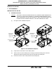


Table Of Contents
- Record of Revisions
- Service Bulletin List
- List of Effective Pages
- Table of Contents
- List of Figures
- Introduction
- Description and Operation
- Test and Fault Isolation
- 1. Inspection and Test Regulatory Requirements
- 2. Inspection and Test Procedures
- A. Checklist
- B. Preparation
- C. Coax Cable and Wiring Connections Inspection – Item 1
- D. Mounting Tray and Hardware Inspection – Item 2
- E. Battery Pack Inspection – Item 3
- F. G-Switch Functional Check – Item 4
- G. Performance Testing Setup
- H. 121.5 MHz Frequency Measurement – Item 5a
- I. Audio Modulation Check – Item 5b
- J. 121.5 MHz Power Output Measurement – Item 5c
- K. 406 MHz Frequency Measurement – Item 5d
- L. 406 MHz Power Output Measurement – Item 5e
- M. Current Draw Test – Item 5f
- N. Digital Message Verification – Item 5g
- O. ELT Reset Check – Item 5h
- P. Installed Transmitter Test – Item 6
- Q. Antenna Test – Item 7
- R. Inspection and Test Documentation – Item 8
- 3. Fault Isolation
- Removal
- Installation
- 1. Regulatory Requirements and Guidelines
- 2. Mounting Tray
- 3. Antenna
- 4. Remote Switch
- 5. Buzzer
- 6. Wiring
- A. General Considerations and Recommendations
- B. Remote Switch Harness Fabrication
- C. ELT D-Sub Plug Installation
- D. Cockpit Remote Switch 9-Pin Plug Installation
- E. Wiring Installation
- F. Antenna Connection
- G. Cockpit Remote Switch Power Connection
- H. Remote Switch Alternate Power Source
- I. Airframe Ground Connections
- J. Buzzer Connections
- K. Remote Switch Final Installation
- 7. ELT Installation
- 8. Battery Pack Installation
- 9. Helicopter Installations - Special Considerations
- Appendix A – ELT Registration
- Illustrated Parts List

ARTEX PRODUCTS / ACR ELECTRONICS, INC
DESCRIPTION, OPERATION, INSTALLATION AND MAINTENANCE MANUAL
ME406 (453-6603), ME406HM (453-6604)
25-62-30
Page 64 of 84
Jun 25/13
(12) Install the strain relief clamp.
Figure 21 D-Sub Plug Assembly
SUBTASK 25-62-30-450-003
D. Cockpit Remote Switch 9-Pin Plug Installation
NOTE
: If moisture intrusion is a possibility, apply a thin bead of RTV over rear of the MOLEX
connector to prevent corrosion buildup. Use Dow Corning RTV-3145 or equivalent.
(1) Insert the wiring pins in the Molex 9-pin cockpit remote switch plug (151-5009), referring to
the wiring diagram appropriate for the installation, as follows:
(a) Insert each harness female pin into the plug, referring to the wire identification and pin
relationships recorded in Step C.(5)(a).
NOTE
: Terminal pins may be removed from the plug using Molex extraction tool
11030002, or equivalent.
(b) Insert the remote switch power wire female pin into Pin 1 or Pin 3 of the plug, as
appropriate for the selected 14V or 28V power source.
(c) Insert the remote switch ground wire into Pin 9 of the plug.
SUBTASK 25-62-30-450-004
E. Wiring Installation
(1) Route the remote switch harness wire bundle and breakout wiring through the airframe.
GROMMET
(RAISED COLLAR END)
4 OR 5-CONDUCTOR CABLE
(HORN CONDUCTOR NOT
SHOWN)
THUMBSCREW (TYP.)
BRACKET WASHER (TYP.)
HOUSING HALF (TYP.)
HARDWARE (TYP.)
15-PIN
D-SUB PLUG
NOTE: STRAIN RELIEF
CLAMP NOT SHOWN