
User guide


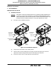


Table Of Contents
- Record of Revisions
- Service Bulletin List
- List of Effective Pages
- Table of Contents
- List of Figures
- Introduction
- Description and Operation
- Test and Fault Isolation
- 1. Inspection and Test Regulatory Requirements
- 2. Inspection and Test Procedures
- A. Checklist
- B. Preparation
- C. Coax Cable and Wiring Connections Inspection – Item 1
- D. Mounting Tray and Hardware Inspection – Item 2
- E. Battery Pack Inspection – Item 3
- F. G-Switch Functional Check – Item 4
- G. Performance Testing Setup
- H. 121.5 MHz Frequency Measurement – Item 5a
- I. Audio Modulation Check – Item 5b
- J. 121.5 MHz Power Output Measurement – Item 5c
- K. 406 MHz Frequency Measurement – Item 5d
- L. 406 MHz Power Output Measurement – Item 5e
- M. Current Draw Test – Item 5f
- N. Digital Message Verification – Item 5g
- O. ELT Reset Check – Item 5h
- P. Installed Transmitter Test – Item 6
- Q. Antenna Test – Item 7
- R. Inspection and Test Documentation – Item 8
- 3. Fault Isolation
- Removal
- Installation
- 1. Regulatory Requirements and Guidelines
- 2. Mounting Tray
- 3. Antenna
- 4. Remote Switch
- 5. Buzzer
- 6. Wiring
- A. General Considerations and Recommendations
- B. Remote Switch Harness Fabrication
- C. ELT D-Sub Plug Installation
- D. Cockpit Remote Switch 9-Pin Plug Installation
- E. Wiring Installation
- F. Antenna Connection
- G. Cockpit Remote Switch Power Connection
- H. Remote Switch Alternate Power Source
- I. Airframe Ground Connections
- J. Buzzer Connections
- K. Remote Switch Final Installation
- 7. ELT Installation
- 8. Battery Pack Installation
- 9. Helicopter Installations - Special Considerations
- Appendix A – ELT Registration
- Illustrated Parts List

25-62-30
Page 69 of 84
Jun 25/13
ARTEX PRODUCTS / ACR ELECTRONICS, INC
DESCRIPTION, OPERATION, INSTALLATION AND MAINTENANCE MANUAL
ME406 (453-6603), ME406HM (453-6604)
(6) Connect the remote switch harness plug to the ELT, as follows:
(a) Press two sealant strips (850-0814) against the male pins of the ELT receptacle with the
tacky side against the pins, while peeling the foam backing off each sealant strip.
NOTE
: Verify sealant strips match the receptacle shape.
NOTE
: Verify the sealant strips are in place on existing installations.
(b) Plug the remote switch harness plug into the ELT receptacle.
(c) Screw the thumbscrews into the ELT receptacle retaining nuts until the plug is seated
properly.
(7) Connect the antenna coax cable to the ELT.
(8) Tie up excess slack in the harness and coax cable, such that they form drip loops.
NOTE
: Steps (1) through (7) are applicable any time the ELT has been removed and
undergoes reinstallation. Step (8) is only applicable at initial installation or if the
wiring or coax cable has been disturbed.
(9) Test the ELT installation in accordance with the requirements of SUBTASK 25-62-30-750-011
on page 40.
NOTE
: It is very important the cockpit remote switch LED immediately begins flashing
continuously upon ELT activation. If the LED fails to start flashing, recheck the
interface wiring and connections between the ELT and the cockpit remote switch.
NOTE
: If verification of the digital message (i.e., 406 MHz burst) is desired, follow the
procedures outlined in SUBTASK 25-62-30-750-009 on page 39.
SUBTASK 25-62-30-450-001
B. Harness ELT D-Sub Plug Sealing
(1) Seal the D-Sub plug at the ELT end to prevent moisture from penetrating the connection, thus
preventing water from beading up and causing bridging between connector pins resulting in
possible activation of the ELT. Use the following procedure:
NOTE
: Perform the sealing process once all tests have been satisfactorily completed and all
harness connections have been verified to be correct.
(a) Disconnect the remote switch harness D-Sub plug from the ELT.
(b) Separate the D-Sub housing halves.
(c) Inject Dow Corning® 4 Electrical Insulating Compound or an equivalent meeting MIL-S-
8660C into the back side of the plug, such that the insulating compound surrounds the
D-Sub pin area and covers the back of the plug.
(d) Reinstall the housing halves.
(e) Inject Dow Corning® 4 Electrical Insulating Compound or an equivalent meeting MIL-S-
8660C around the male pins of the ELT receptacle.
(f) Connect the remote switch harness plug to the ELT.