
User's Manual


GRN4-610 Chapter 2: Functional Description 19 of 73
Rotor and Cutters
The material is ground between the knives assembled on the rotor and the stator knives
which are mounted in a fixed position in the machine lower section. All rotors are
equipped with square knives. These knives make light work of the heaviest pieces. The
knives have four corners, so that they can be easily turned once a comer has worn off.
The design of the rotor has a significant influence on the quality of the grinding process
and its results. The rotor construction, the type of knife mounting and the number of
knives have all been exactly matched to your task allocation.
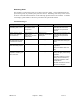
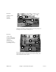
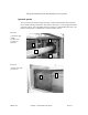
Illustration:
(1) Rotor knife
(2) Stator knife
(3) Discharge area
Due to the compact design this machine can only be used for screen-less operations!
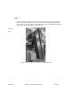
The rotor is accessible after opening the lower housing flap or the upper housing flap.
The rotor is arranged on roller bearings, which are situated outside the housing. The "V"-
belt pulley is attached by means of a taper bush to the rotor axis. The rotor is dynamically
counter balanced and has vibration-free concentricity.
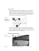
Discharge of grinding material
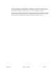
Illustration:
Conveyor belt discharge
2
1
3