Outdoor Mini Dome & Outdoor Mini Fisheye Dome Hardware Manual E918, E918M, E919, E919M, E920, E920M, E921, E921M, E922, E922M, E923, E923M Ver.
Hardware Manual Table of Contents Precautions 4 Safety Instructions ........................................................................... 6 Introduction 7 List of Models.................................................................................... 7 Package Contents............................................................................. 9 Physical Description ...................................................................... 10 E918 / E920 / E922 ..................................
Hardware Manual How to Adjust the Fisheye View Orientation (for E919, E921, E923 only) ........................................................ 26 How to Connect Audio In Device ................................................... 27 How to Replace the Dome Cover ................................................... 28 Accessing the Camera 31 Configure the IP Addresses ........................................................... 31 Using DHCP Server to Assign IP Addresses ................................
Hardware Manual Precautions Read these instructions You should read all the safety and operating instructions before using this product. Heed all warnings You must adhere to all the warnings on the product and in the instruction manual. Failure to follow the safety instruction given may directly endanger people, cause damage to the system or to other equipment.
Hardware Manual Federal Communications Commission Statement This equipment has been tested and found to comply with the limits for a class B digital device, pursuant to Part 15 of the FCC Rules. These limits are designed to provide reasonable protection against harmful interference in a residential installation. This equipment generates, uses, and can radiate radio frequency energy and, if not installed and used in accordance with the instructions, may cause harmful interference to radio communications.
Hardware Manual Safety Instructions Cleaning Disconnect this video product from the power supply before cleaning. Attachments Do not use attachments not recommended by the video product manufacturer as they may cause hazards. Water and Moisture Do not use this video product near water, for example, near a bathtub, washbowl, kitchen sink, or laundry tub, in a wet basement, or near a swimming pool and the like.
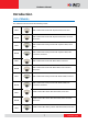
Hardware Manual Introduction List of Models This hardware manual contains the following models: E918 E918M 3MP Outdoor Mini Dome with Superior WDR, Fixed lens 3MP Outdoor Mini Dome with Superior WDR, M12 connector, Fixed lens E919 3MP Outdoor Mini Fisheye Dome with Superior WDR, Fixed lens E919M 3MP Outdoor Mini Fisheye Dome with Superior WDR, M12 connector, Fixed lens E920 E920M E921 E921M E922 E922M E923 5MP Outdoor Mini Dome with Basic WDR, Fixed lens 5MP Outdoor Mini Dome with Basic WD
Hardware Manual E923M 10MP Outdoor Mini Fisheye Dome with Basic WDR, M12 connector, Fixed lens From the installation perspective, the above models are very similar; therefore one manual is used for all of them. 8 www.acti.
Hardware Manual Package Contents Check if the camera package comes with the following items: Camera Camera E918, E918M, E920, E920M, E922, E922M E919, E919M, E921, E921M, E923, E923M or Drill Template Screw Kit Drill Template Cable Gland Hexagon Screwdriver (Not available in E9xxM models) Quick Installation Guide Warranty Card IMPORTANT: When the camera is taken out from the box, the lens cover is covered by a thin film. DO NOT remove this film.
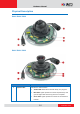
Hardware Manual Physical Description E918 / E920 / E922 E919 / E921 / E923 Item 1 System LEDs Description Indicates the camera status: Amber LED: Blinks when network activity is in progress. Blue LED: Lights up when the camera is powered up and goes off again after the boot up process is complete. Green LED: Lights up when the camera is connected to a network. 10 www.acti.
Hardware Manual Item 2 Audio Input Description Connects to audio input devices, such as a microphone with built-in amplifier, etc. See How to Connect Audio In Device on page 27 for more information. NOTE: The microphone must have a built-in amplifier. Connecting an ordinary microphone will dwarf sounds and will result in inaudible recording. 3 4 Ethernet Port Connects to a network using an Ethernet cable with RJ-45 (RJ-45) connector.
Hardware Manual E918M / E920M / E922M E919M / E921M / E923M Item 1 System LEDs Description Indicates the camera status: Amber LED: Blinks when network activity is in progress. Blue LED: Lights up when the camera is powered up and goes off again after the boot up process is complete. Green LED: Lights up when the camera is connected to a network. 12 www.acti.
Hardware Manual Item 2 Audio Input Description Connects to audio input devices, such as a microphone with built-in amplifier, etc. See How to Connect Audio In Device on page 27 for more information. NOTE: The microphone must have a built-in amplifier. Connecting an ordinary microphone will dwarf sounds and will result in inaudible recording. 3 Ethernet Port (M12) Connects to a network using an Ethernet cable with M12 connector. The camera uses the female M12 connector with D-coding and PoE type A.
Hardware Manual Mounting Options Select the most suitable solution for your installation environment.The camera can be mounted by either of the following methods: Mount Types Accessories Surface Mount Suitable when mounting the camera directly on walls or ceilings without additional mounting accessories. See Installation Procedures on page 15 for more information. Gangbox Suitable when mounting the camera on a 4” Round or 4” Octagon Gangbox.
Hardware Manual Installation Procedures This section describes procedures in mounting the camera on a flat surface. NOTE: The camera images on this documentation are for reference only and may be different from the actual camera. Step 1: Prepare for Installation 1. Before installing the camera, prepare the additional accessories required for installation.
Hardware Manual Step 2: Open the Dome Cover 1. Loosen the three (3) screws using the bundled hex screwdriver. 2. Lift to remove the dome cover. NOTE: The dome cover is attached to the camera body by a string, do not abruptly lift the dome cover! A desiccant bag is attached underneath the dome cover. DO NOT remove the desiccant bag to keep the camera interior parts dry. 16 www.acti.
Hardware Manual Step 3: Route the Cables Determine whether the cable will pass through a hole on the surface or be routed along the surface: If the cable will pass through a hole on the surface: 1. Drill the hole for the cable on the surface. Drill cable hole within this block. 2. Route the cable from the network side through the hole and connect it to the Ethernet port of the camera.
Hardware Manual Step 4: Install the Camera 1. If necessary, insert a memory card into the memory card slot of the camera. See How to Insert the Memory Card on page 25 for more information. 2. Install the camera to the surface using the three (3) bundled screws. NOTE: Please make sure the screw is flat on the plate. 18 www.acti.
Hardware Manual Step 5: Waterproof the Cable Connection Depending on the camera model, the Ethernet cable or the “pigtail” of the camera may either have the RJ-45 or M12 connector. M12 Ethernet Cable (for E9xxM models only) Typical M12 Ethernet cable has waterproof connection. Simply connect and screw the cable connectors to make the connection waterproof. Make sure the connectors are secured tightly. 19 www.acti.
Hardware Manual RJ-45 Ethernet Cable (for E9xx models only) When using the RJ-45 Ethernet cable, follow the procedures below to waterproof the cable connection: 1. Detach the cable gland as shown below. Gland Body Clamping Nut Sealing Rubber and Claw 2. On the network side cable, insert the clamping nut through the Ethernet cable. 3. Insert the sealing rubber and claw through the Ethernet cable. 20 www.acti.
Hardware Manual 4. Make sure the bundled rubber ring is completely aligned on the gap on the gland body. 5. Attach the gland body to the Ethernet port of the camera. IMPORTANT! Make sure the rubber ring is completely aligned and flat on the gland body to avoid possible water leakage. 6. Connect the RJ-45 connector of the network cable to the Ethernet port of the camera. 21 www.acti.
Hardware Manual 7. Insert the sealing rubber and claw into the cable gland body. 8. Attach the clamping nut to the cable gland body. Make sure the clamping nut is tightly secured and the rubber is squeezed in to avoid water leakage. DISCLAIMER: ACTi will not be responsible for camera damage caused by water entering the cable connections. 22 www.acti.
Hardware Manual Step 6: Connect to Network Connect the other end of the network cable to a switch or injector. Then, connect the switch or injector to a network or PC and a power source. See Power-over-Ethernet (PoE) example connection diagram below.
Hardware Manual Step 8: Close the Dome Cover 1. Align cable tab side of the dome cover to the direction of the network cable. 2. Tighten the three (3) screws using the supplied hex screwdriver to attach the dome cover. 3. Remove the thin film. Final installation should look similar to the illustration below. 24 www.acti.
Hardware Manual Other Adjustments and Accessories How to Install / Remove the Memory Card How to Insert the Memory Card 1. Loosen the three (3) screws to remove the dome cover. 2. Insert the memory card into the card slot with the metal contacts facing the bottom side of the camera. 3. Push the card completely until it clicks into place. 4. Attach the dome cover to the camera and tighten the three (3) screws.
Hardware Manual How to Adjust the Fisheye View Orientation (for E919, E921, E923 only) 1. Open the dome cover. 2. Loosen the three (3) screws securing the lens. 3. Turn the lens to adjust the viewing orientation. The arrow on the lens indicates the top side orientation. 4. Once done, tighten the three (3) screws to fix the lens position. 5. Close the dome cover. 26 www.acti.
Hardware Manual How to Connect Audio In Device The camera comes with an audio jack where an audio input device, such as a microphone with a built-in amplifier, can be connected. The audio-in jack is covered by a rubber protection. WARNING: Do not remove this rubber protection if the audio-in jack will not be used to avoid water or dust from entering the jack. To connect an audio input device, do the following: 1. Pull to remove the rubber protection. 2. Connect the audio input device.
Hardware Manual How to Replace the Dome Cover For more discrete surveillance needs, the pre-installed dome cover can be replaced with a smoked, vandal proof dome cover. The smoked dome cover is an optiona accessory; contact your sales agent to purchase. To replace the dome cover, follow the procedures below: 1. Open the dome cover. 2. Remove the six (6) screws securing the dome cover bracket. Note that one (1) screw is used as a hook to attach the dome cover to the camera body. 3.
Hardware Manual 4. Remove the black rubber from the transparent dome cover and place the black rubber to the replacement dome cover. 5. Install the replacement dome cover and then the bracket. 6. Align the screw holes and secure the five (5) screws first. Take note of the screw hole which must not be screwed at this point. 29 www.acti.
Hardware Manual 7. Insert the screw to the eyelet of the camera hook. 8. Attach the last screw to the dome cover bracket. 9. Close the dome cover. 30 www.acti.
Hardware Manual Accessing the Camera Configure the IP Addresses In order to be able to communicate with the camera from your PC, both the camera and the PC have to be within the same network segment. In most cases, it means that they both should have very similar IP addresses, where only the last number of the IP address is different from each other. There are 2 different approaches to IP Address management in Local Area Networks – by DHCP Server or Manually.
Hardware Manual By double-clicking with the left mouse on the camera model, it is possible to automatically launch the default browser of the PC with the IP address of the target camera filled in the address bar of the browser already. If you work with our cameras regularly, then there is even a better way to discover the cameras in the network – by using IP Utility.
Hardware Manual Using the Default Camera IP Address If there is no DHCP server in the given network, the user may have to assign the IP addresses to both PC and camera manually to make sure they are in the same network segment. When the camera is plugged into network and it does not detect any DHCP services, it will automatically assign itself a default IP: 192.168.0.100 Whereas the default port number would be 80.
Hardware Manual Manually adjust the IP addresses of multiple cameras: If there are more than 1 camera to be used in the same local area network and there is no DHCP server to assign unique IP addresses to each of them, all of the cameras would then have the initial IP address of 192.168.0.100, which is not a proper situation for network devices – all the IP addresses have to be different from each other.
Hardware Manual Access the Camera Now that the camera and the PC are both having their unique IP addresses and are under the same network segment, it is possible to use the Web browser of the PC to access the camera. You can use any of the browsers to access the camera, however, the full functionality is provided only for Microsoft Internet Explorer.
Hardware Manual The following examples in this manual are based on Internet Explorer browser in order to cover all functions of the camera. Assuming that the camera’s IP address is 192.168.0.100, you can access it by opening the Web browser and typing the following address into Web browser’s address bar: http://192.168.0.100 Upon successful connection to the camera, the user interface called Web Configurator would appear together with the login page.
Copyright © 2014, ACTi Corporation All Rights Reserved 7F, No. 1, Alley 20, Lane 407, Sec. 2, Ti-Ding Blvd., Neihu District, Taipei, Taiwan 114, R.O.C. TEL : +886-2-2656-2588 FAX : +886-2-2656-2599 Email: sales@acti.