V.
Table of Contents Proprietary Notice and Disclaimer ..................................................... 2 Contacting Actiontec Customer Support ............................................ 3 Introduction ........................................................................................... 3 Do This First ........................................................................................... 4 For Windows 95 and Windows 98 Installations .................................. 4 For Windows NT 4.
Introduction Thank you for purchasing the Actiontec 56K ISA Advantage V.90 internal modem. The Advantage incorporates the latest technology in host-based V.90 modems. This new technology provides vast improvements in both the performance and the capabilities of personal computer fax/modems. Controller-less modems, also known as Win Modems or Windows Modems, utilize your computer’s Central Processing Unit (or CPU) to perform some of their functions.
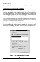
Do This First Please read the following tips before attempting to install your new modem. For Windows 95 and Windows 98 Installations Be sure to remove all other modem drivers from your operating system. To do this, right-click My Computer, choose Properties from the menu that appears, then click on the Device Manager tab. Double-click the Modems icon in the list of devices to show the modems installed. Click once on the icon next to any modems in this list to select them.
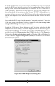
If you are going to use the Telephone Answering Machine (TAM) functions of the modem and you are running Windows 95, you need to install a software component called Unimodem V. If you have Windows 95 OEM Service Release 2 (Version 4.00.950 B) or a later version of Windows, this component comes standard as part of the operating system. To find out which version of Windows 95 you are using, right click the My Computer icon on the desktop, and choose Properties from the menu that appears.
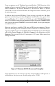
To disable COM2, boot your system and enter your BIOS setup. You can normally invoke the BIOS setup menu by pressing a key or a combination of keys at the first boot up screen. Some of the common keys are DELETE, F1, F2, CTRL+ALT+S, CTRL+ALT+ESC. (Watch the text that appears as you turn your computer on-there will probably be instructions on how to enter “SETUP”--following these instructions will give you access to the BIOS.
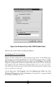
Figure 3b: Windows 95 (or 95A) COM2 Disable Panel Proceed to the section titled “Installing the Modem.” For Windows NT 4.0 Installation Remove all other modem drivers from your operating system. On the Start menu, click Settings then click Control Panel. In Control Panel, double-click on the Modems icon. Select the modem you wish to remove and click Remove. Turn off the computer and physically remove the modem from your system. Do not install your new modem at this time. Follow the procedures below.
Before installing the modem, you must enable ISA Plug-N-Play support within Windows NT. First set your system BIOS to “PnP OS” and then insert the Windows NT 4.0 CD-ROM into your systems CD-ROM Drive. The Startup window for Windows NT 4.0 should appear after a few moments. Click Browse This CD. Doubleclick the Drvlib folder. From the new panel double-click on the Pnpisa folder. Another panel will appear. Double-click on the x86 folder. The contents of this folder should contain a file labeled Pnpisa.
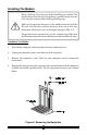
Installing The Modem Always discharge static electricity before handling your modem. You may discharge static electricity by touching a grounded metal structure or by using any commercially available grounding strap. Make sure the expansion slot type is 16-bit, which has two slots to fit the ISA card. 8-bit slots have only one connector. If you use an 8-bit slot, the modem will not have access to the higher interrupts (IRQ 9-12).
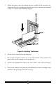
5. Firmly, but gently, insert the modem into the available 16-bit expansion slot. Ensure that the card is seated properly before securing it with the screw removed in Step 4, as shown in the following diagram: Figure 6: Installing The Modem 6. Put the chassis cover back on the computer. 7. Be sure that all power switches are in the OFF position, then reconnect the power cables to the computer and its peripherals. 8. Connect the telephone line cable to the “Line (Telco)” jack as shown in Figure 7. 9.
Connecting Devices To The Modem Fig.7: Connecting Devices On the rear panel of your modem are input jacks to connect devices to the modem. As shown in the diagram, there are jacks for connection to a “phone” and to a phone “line.” The connector labeled Line (Telco) is meant to be connected to a standard analog phone line. To help reduce the load on your phone line, it is recommended that the modem be the only device connected.
Configuring Windows 95 Step 1 Upon startup, Windows 95 detects the modem and displays the New Hardware Found dialog box. Select “Driver from disk provided by hardware manufacturer” then click OK. Step 2 Type your CD-ROM drive’s drive letter into the Copy manufacturer’s files from box. Insert the Installation CD-ROM and click OK. Step 3 If Windows asks for an installation disc, click OK and type the drive letter for you CD-ROM drive in the dialog box that appears and click OK.
Step 4 After the installer has copied the .INF files to the hard disk, a New Hardware Found dialog box should appear prompting for the “Wave Device for Voice Modem”. Click OK. (See “Do This First” for information on UNIMODEM.INF if this screen does not appear). Step 5 Click OK to copy the Wave Device .INF file from the CD-ROM drive to the hard drive. Windows may request its own installation diskettes for some files. Insert the Windows CD-ROM as required.
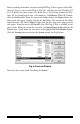
Step 6 To determine what COM port and IRQ is assigned to the modem in Windows 95, click on the Modems icon in Control Panel and select the Diagnostic tab. Click on the COM Port icon and then on the More Info button to view the modem properties.
Configuring Windows 95 OEM SR2 Step 1 Upon startup, Windows 95 detects the modem and launches the Update Device Driver Wizard dialog box. Insert the modem’s installation CD-ROM and click Next. Step 2 After Windows 95 has found the updated drivers for your modem, click Finish.
Step 3 If Windows asks for its own installation disc, click OK. Insert the requested CD-ROM, type the drive letter of your CD-ROM in the dialog box that appears next, and click OK. Step 4 After the Wizard has copied the .INF files to the hard disk, it should detect “Wave Device for Voice Modem” and prompt for its driver. Click Next. . Step 5 Click Finish to copy the Wave Device .INF file from the CD-ROM drive to the hard drive. Windows may request its own installation diskettes for some files.
Step 6 To determine what COM port and IRQ is assigned to the modem in Windows 95, click on the Modems icon in Control Panel and select the Diagnostics tab. Select your modem and then click on the More Info button to view the modem properties.
Step 7 Remember this COM port number. When you install your Data/Fax software or internet browser program, you may need to set your modem port location to this same number.
Configuring Windows 98 Step 1 After installing the modem hardware, turn on your computer. Windows will detect the modem and start the Add New Hardware Wizard. Click Next. Step 2 The Add New Hardware Wizard will ask if you would like it to “search for the best driver for your device (Recommended).” If this option is not already selected, click it, then click Next.
Step 3 The Wizard will ask where it should search for the drivers. Click “CDROM drive” to select it. Make sure the installation CD-ROM is in the CDROM drive. Click Next. Step 4 Next the Wizard will identify the driver file and report its location on the CD-ROM drive. Click the Next button to copy and install the driver.
Step 5 After copying the files to your hard drive, the wizard will report that it is finished installing the drivers for the modem. Click Finish. Step 6 Windows will now detect a “Wave Device for Voice Modem” and start the Add New Hardware Wizard again to find the drivers for the voice capabilities of your modem. Click Next.
Step 7 The Add New Hardware Wizard will ask if you would like it to “search for the best driver for your device (Recommended).” If this option is not already selected, click it, then click Next. Step 8 The Wizard will ask where it should search for the drivers. Click “CDROM drive” to select it. Make sure the installation CD-ROM is in the CDROM drive. Click Next.
Step 9 Next the Wizard will identify the driver file and report its location on the CD-ROM drive. Click the Next button to copy and instal the driver. Step 10 Windows will copy and install the files, and then display the dialog box below, reporting that the process has finished. Click Finish.
Step 11 Windows will finish loading. To make sure your modem has been installed correctly, click Start on the taskbar. On the Start menu, click Settings, then click Control Panel. In Control Panel, double-click the Modems icon, then click the Properties tab to bring it to the front. On the Modems Properties tab, click the COM port number (COM 3 in the illustration below) to select the modem, then click More Info.
Step 12 Check that the More Info dialog box that appears on your screen matches the illustration below. Make a note of the interrupt (also known as an IRQ) and the port number. These will be needed to configure your communications software. Your modem is now installed and configured for use with Windows 98.
Configuring Windows NT 4.0 Before installing the modem, make sure you have installed the PnP ISA Enabler and the latest Service Pack upgrade to Windows NT 4.0. See the section titled “Do This First” for details. Step1 Install the modem hardware and turn on your computer. Upon startup, Windows NT 4.0 detects your modem and displays the New Hardware Found dialog box.Select “Driver from disk provided by hardware manufacturer” then click OK. Note: Windows NT may detect other devices in your computer.
Step 4 A panel for selecting the device to be installed should appear. Highlight the “V.90 Windows Modem (LHT)” selection and click OK. Step 5 If you see the following dialog box, you will need to set the configuration manually.
Step 6 Select the Resource Settings which do not cause any conflicts with other devices. Step 7 Restart your computer. Step 8 Click on the Modems icon in the Control Panel. Verify that Windows NT has correctly found the modem. Step 9 If you wish to use your modem to dial into a Windows NT Remote Access Server or wish to connect to the Internet, you will need to configure Dialup Networking. If you do not see the Remote Access Setup Panel installation, In Control Panel double-click the Network icon.
Step 10 At the Remote Access Setup dialog box, click on Add. Select the Remote Access Setup device you wish to add and Click OK. Step 11 Click Continue to finish the installation. Step 12 After Windows NT has completed the binding process, allow Windows NT to shut down and restart the computer.
Installing and Configuring Communications Software If your modem came with a communications software package, it is strongly recommended that you use this software for your modem. It’s default installation parameters have been specially configured to work with this modem. The Users Guide for this program can be found inside the modem package. It can be supplied in either soft-bound copy or on CD-ROM (depending on the model you purchased). Some configurations are packaged without communications software.
call is detected. The modem converts the digital information contained in the .wav file into an audio signal which is then sent over the phone line. The person calling hears your outgoing message and responds with an incoming message. The sequence of recording an incoming message is the reverse of an outgoing message. The modem converts the audio signal into a digital format and sends it to the application program. The application program then formats and stores the incoming message as a .wav file.
Troubleshooting This section lists some common problems and offers suggestions for a solution. It is important to remember that this modem is a Windows 95/98/NT based modem and requires 32bit virtual device drivers. It therefore cannot work in Windows 3.1 which cannot use these drivers. The modem also cannot work in DOS regardless of version. It is a purely Plug-N-Play device and has no provisions for manual configuration.
Device Usage box and make sure “Disable in this hardware profile” is not selected. (Windows 95 OEM SR2 and Windows 98 only). Make a note of the COM port and IRQ the modem is using. Errors reported in the Device Status box generally refer to conflicts. Click the Resources tab and read the “Conflicting Device List.” If a conflict is present, click to deselect “Use automatic Setting” and select a configuration that does not cause conflicts. Manually change the address and IRQ settings if needed.
If you receive an error message or the panel is blank, go to the section of this manual “Does Not Install.” Step 4: Does Not Install The most likely reason for a non-installation in Windows 95 or 98 is a lack of IRQ resources. The modem needs one IRQ and one COM Port in order to function. Computers are usually equipped with a sound card, CD-ROM drive, Hard-drive, floppy drive, video card, two COM ports, one LPT port, keyboard, and a mouse.
Modems section after you have deleted it from the Device Manager. If it is, this could be a sign that your Plug-N-Play settings are not correct. See “Does Not Install” for information about Plug-N-Play.) 3. Close all open programs and return to the Windows desktop. On the Start menu, click Find, then click Files or Folders and search for the files listed below. Type in the name and extension of each and click Find.
At the Advanced settings window, type the following in the “Containing text” field: LT Win Modem. Click Find Now. When a file is found, it will have the name “oem#.inf.” Delete only an oem inf file. To delete a file, highlight the file name by clicking once and then choose Delete from the File menu. After the file is deleted, you now need to find the other inf file. Go to the Advanced tab and type “LT_Win_Modem” in the “Containing text” field: After Windows finds the other file, delete it as before.
Common Problems No Dialtone Error Make sure you have connected the phone cable into the right connector on the back of the modem. See “Figure 7: Connecting Devices.” You may have too many devices connected to the phone line. Remove all other equipment. Your modem may not recognize overseas dialtone. Use the AT command string “ATX0” to have the modem ignore the dialtone before dialing.
when the modem is in use. This includes extension phones, answering machines, cordless phone bases, caller ID boxes and their cables. This reduces the load on your phone line and keeps signal attenuation to a minimum. Keep the length of your phone line cable to 10 feet or less. If necessary, move the computer closer to the phone socket. Don’t lay your cabling close to an electrical appliance like a refrigerator or air conditioner unit.
Appendix A: AT Command Set AT Commands AT commands are issued to the modem to control the modem’s operation and software configuration. AT commands can only be entered while the modem is in command mode. Enter AT commands by typing: ATXn where X is the AT command, and n is the specific value for that command. Press ENTER. Any command issued is acknowledged with a response in either text or numeric values known as result codes.
Bn Communication Standard Setting This command determines CCITT vs. Bell standard. C ommand Effect B0 Selects C C ITT V.22 mode when the modem i s at 1200 bi ts/s. B1 Selects Bell 212A when the modem i s at 1200 bi ts/s (default). B2 Unselects V23 reverse channel (same as B3). B3 Unselects V23 reverse channel (same as B2). B 15 Selects V.21 when the modem i s at 300 bi ts/s. B 16 Selects Bell 103J when the modem i s at 300 bi ts/s (default).
Dn Dial This command instructs the modem to begin the dialing sequence. The dial string (n, including modifiers and the telephone number) is entered after the ATD command. A dial string can be up to 40 characters long. Any digit or symbol (0-9, *, #, A, B, C, D) may be dialed as touch-tone digits. Characters such as spaces, hyphens, and parentheses do not count, they are ignored by the modem and may be included in the dial string to enhance readability.
En Echo Command This command controls whether or not the characters entered from your computer keyboard are echoed back to your monitor while the modem is in command mode. C ommand Effect E0 D i sables echo to the computer. E1 Enables echo to the computer (default). Result Codes: OK n = 0, 1 ERROR Otherwi se Fn Online Data Character Echo Command This command determines if the modem will echo data from the DTE. This modem does not support the F0 version of the command.
Result Codes: OK n = 0, 1 ERROR Otherwi se In Request ID Information This command displays specific product information about the modem. C ommand Effect IO Returns default speed and controller fi rmware versi on. (same as I3) I1 C alculates ROM checksum and di splays i t on the D TE (e.g., 12AB). I2 Performs a ROM check and calculates and veri fi es the checksum di splayi ng OK or ERROR. I3 Returns the default speed and the controller fi rmware versi on.
Result Codes: OK n = 0, 1, 2, 3 ERROR Otherwi se Mn Monitor Speaker Mode This command turns the speaker on or off. C ommand Effect M0 The speaker i s off. M1 The speaker i s on unti l the modem detects the carri er si gnal (default). M2 The speaker i s always on when modem i s off-hook. M3 The speaker i s on unti l the carri er i s detected, except whi le di ali ng.
On Return On-line to Data Mode C ommand Effect O0 Instructs the modem to exi t on-li ne command mode and return to data mode (see AT Escape Sequence, +++). O1 Thi s command i ssues a retrai n before returni ng to onli ne data mode. O3 Thi s command i ssues a rate renegoti ati on before returni ng to onli ne data mode. Result Codes: OK n = 0, 1, 3 ERROR Otherwi se P Select Pulse Dialing This command configures the modem for pulse (non-touch-tone) dialing.
Vn DCE Response Format This command controls whether result codes (including call progress and negotiation progress messages) are displayed as words or their numeric equivalents. C ommand Effect V0 Not supported. Results are always text. V1 D i splays result codes as text (default). Result Codes: OK n = 0, 1 ERROR Otherwi se Wn Result Code Option C ommand Effect W0 C ONNEC T result code reports D TE speed. D i sable protocol result codes. W1 C ONNEC T result code reports D TE speed.
Xn Result Code Selection and Call Progress Monitoring This command enables tone detection options used in the dialing process. As these functions are chosen, the result codes are also affected. Therefore, this command is frequently used to control the modem chipset’s responses. The primary function of this control is to control the modem chip set’s call response capabilities.
Busy Tone Detect Busy Tone D etect Effect D i sabled The modem i gnores any busy tones i t recei ves. Enabled The modem moni tors for busy tones. Result Codes: OK n = 0, 1, 2, 3, 4, 5, 6, 7 ERROR Otherwi se Yn Long Space Disconnect Long space disconnect is always disabled. C ommand Effect Y0 D i sable long space di sconnect (default). Y1 Enable long space di sconnect. (Not supported.
Result Codes: OK n=1 ERROR Otherwi se &Cn Data Carrier Detect (DCD) Control Data Carrier Detect is a signal from the modem to your computer indicating that the carrier signal is being received from a remote modem. DCD normally turns off when the modem no longer detects the carrier signal. C ommand Effect &C0 The state of the carri er from the remote modem i s i gnored. D C D ci rcui t i s always on.
&Fn Load Factory Settings This command loads the configuration stored and programmed at the factory. This operation replaces all of the command options and the S-register settings in the active configuration with factory values. C ommand Effect & F0 Recall factory setti ng as acti ve confi gurati on. (default) &Gn V.22bis Guard Tone Control This command determines which guard tone, if any, to transmit while transmitting in the high band (answer mode). This command is only used in V.22 and V.
&Kn Local Flow Control Selection C ommand Effect &K0 D i sable flow control. &K1 Reserved. &K2 Reserved. &K3 Enable RTS/C TS flow control (default). &K4 Enable XON/XOFF flow control. Result Codes: OK n = 0, 3, 4 ERROR Otherwi se &Mn Asynchronous Communications Mode C ommand Effect &M0 Asynchronous mode (default). &M1 Reserved. &M2 Reserved. &M3 Reserved. &M4 Reserved.
&Qn Asynchronous Communications Mode C ommand Effect &Q0 Asynchronous Mode, buffered. Same as \N0. &Q1 Reserved. &Q2 Reserved. &Q3 Reserved. &Q4 Reserved. &Q5 Error C ontrol Mode, buffered (default). Same as \N3. &Q6 Asynchronous Mode, buffered. Same as \N0. &Q7 Reserved. &Q8 MNP error control mode. If an MNP error control protocol i s not establi shed, the modem wi ll fallback accordi ng to the current user setti ng i n S36. &Q9 V.42 or MNP error control mode.
&V0 View Active Configuration and Stored Profile This command is used to display the active profiles.
Option Selection AT Cmd No Carrier Disc DTMF Dial Speed Escape GuardTime Data Calling Tone Line Rate DSVD mode 2000 msec 95 msec 1000 msec Disabled 33600 Disabled S10 S11 S12 S35 S37 -SSE Stored Phone Numbers &Z0= &Z1= &Z2= &Z3= OK &Wn Store Current Configuration This command stores certain command options and S-register values into the modem’s nonvolatile memory. The ATZ command or a powerup reset of the modem restores this profile.
&Zn=x Store Telephone Number This command is used to store up to four dialing strings in the modem’s nonvolatile memory for later dialing. The format for the command is &Zn = ”stored number” where n is the location 0?3 to which the number should be written. The dial string may contain up to 40 characters. The ATDS = n command dials using the string stored in location n.
\G Modem Port Flow Control C ommand Effect \G0 Returns an OK for compati bi li ty (default). \G1 NOT SUPPORTED responds ERROR. Result Codes: OK n=0 ERROR Otherwi se \J Adjust Bits/s Rate Control When this feature is enabled, the modem emulates the behavior of modems that force the DTE interface to the line speed. C ommand Effect \J0 Turn off feature (default). \J1 Turn on feature.
The second case is where the modem is in the on-line command state (waiting for AT commands) during a data connection, and the \B is received in order to send a break to the remote modem: C ommand Effect \K0 C lear data buffers and send break to remote modem. \K1 C lear data buffers and send break to remote modem. (Same as 0.) \K2 Send break to remote modem i mmedi ately. \K3 Send break to remote modem i mmedi ately. (Same as 2.) \K4 Send break to remote modem i n sequence wi th data.
\Nn Error Control Mode Selection This command determines the type of error control used by the modem when sending or receiving data. C ommand Effect \N0 Buffer mode. No error control (same as &Q6). \N1 D i rect mode. \N2 MNP or di sconnect mode. The modem attempts to connect i n MNP 2-4 error control procedure. If thi s fai ls, the modem di sconnects. Thi s i s also known as MNP reli able mode. \N3 V.42, MNP, or buffer (default). The modem attempts to connect i n V.42 error control mode.
Result Codes: OK n = 0, 1, 3 ERROR Otherwi se \Rn Ring indicator signal off after the telephone call is answered (Compatibility command) C ommand Effect \R0 Ri ng i ndi cator si gnal i s off after the telephone call i s answered Result Codes: OK n=0 ERROR Otherwi se \Tn Inactivity Timer This command specifies the length of time (in minutes) that the modem will wait before disconnecting when no data is sent or received. A setting of zero disables the timer.
Result Codes: OK n = 0, 1, 2 ERROR Otherwi se \Xn XON/XOFF Pass Through C ommand Effect \X0 Modem processes XON/XOFF flow control characters locally (default) \X1 Modem processes and pass XON/XOFF flow control characters Result Codes: OK n = 0, 1 ERROR Otherwi se -Cn Data Calling Tone Data Calling Tone is a tone of certain frequency and cadence as specified in V.25 which allows remote Data/FAX/Voice discrimination. The frequency is 1300 Hz with a cadence of .5 s on and 2 s off.
-V90=x V.90 Downstream Rate and Control Use this command to enable/disable V.90 connection and to control V.90 connection rates. The command syntax is AT-V90=x. Where x is a value from the list below. %B AT-V90=n D ownstream Rate 0 V.
%Cn Enable/Disable Data Compression Enables or disables data compression negotiation on an error corrected link. C ommand Effect %C 0 D i sables data compressi on %C 1 Enables both V.42 bi s and MNP 5 data compressi on Result Codes: OK n = 0, 1 ERROR Otherwi se AT Commands for Testing and Debugging The following commands are to be used for testing and debugging only and are not meant for general use.
&Tn Self-Test Commands This command allows the user to perform diagnostic tests on the modem. These tests can help to isolate problems when experiencing periodic data loss or random errors. C ommand Effect &T0 Abort. Stops any test i n progress. &T1 Local analog loop. Thi s test veri fi es modem operati on, as well as the connecti on between the modem and computer. Any data entered at the local D TE i s modulated, then demodulated, and returned to the local D TE.
Description Example Comments Initial Receive Carrier Rate 33600 The download connection rate after initial negotiation. Final Transmit Carrier Rate 33600 The last upload connection rate. Final Receive Carrier Rate 33600 The last download connection rate. Protocol Negotiation Result V.42 Possible results are: V.42, MNP or noEC Data Compression Result V.42bis Possible results are: V.42bis, MNP5 or no Compression.
Description Example Comments Call Termination Cause 0 0 -Call Terminated by Local modem 1 -Call Terminated by Remote modem 2 -No Answer - the Remote modem did not answer 3 -Training Failure - the modems failed to negotiate V.34 or 56K protocols. 4 -Protocol Failure - the modems failed to negotiate V.42 protocol. Robbed-Bit Signaling (56K only) 6 The number of robbed bits detected. Digital Loss 0 Digital Loss in dB. Remote Server ID XXX ID number of remote server.
S1 Ring Counter Range: Default: Units: 0−255 0 rings This register, Ring Counter, is read only. The value of S1 is incremented with each ring. If no rings occur over a six second interval, this register is cleared. S2 AT Escape Character (user defined) Range: Default: Units: 0−255 43 ASCII This register determines the ASCII valued used for an escape sequence. The default is the + character. The escape sequence allows the modem to exit data mode and enter command mode when on-line.
nous only. The modem will not recognize the backspace character if it is set to a value that is greater than 32 ASCII. This character can be used to edit a command line. When the echo command is enabled, the modem echoes back to the local DTE the backspace character, an ASCII space character, and a second backspace character. This means a total of three characters are transmitted each time the modem processes the backspace character.
S10 Automatic Disconnect Delay Range: Default: Units: 1-254 20 0.1 seconds This register sets the length of time, in tenths of a second, that the modem waits before hanging up after a loss of carrier. This allows for a temporary carrier loss without causing the local modem to disconnect. The actual interval the modem waits before disconnecting is the value in register S10. S11 DTMF Dialing Speed Range: Default: Units: 50-150 95 0.
S21 V.24/General Bit Mapped Options Status Indicates the status of command options. Only bits 3, 4 and 5 are used, read only. Bits 3-4 DTR behavior (&Dn) 0 = &D0 selected 1 = &D1 selected 2 = &D2 selected (Default) 3 = &D3 selected Bit 5 DCD behavior (&Cn) 0 = &C0 selected 1 = &C1 selected (Default) Default: 48 (00110000b) S22 Results Bit Mapped Options Status Indicates the status of command options. Only bits 4, 5 and 6 are used, read only.
S28 V.34 Modulation Enable/Disable 0 = disabled, 1-255 = enabled, Range: 0-255 Default: 1 This register enables/disables V.34 modulation. S30 Inactivity Timer Range: 0-255 Default: 0 Units: minutes S30 specifies the length of time (in minutes) that the modem will wait before disconnecting when no data is sent or received. This function is only applicable to buffer mode. S32 Synthetic Ring Volume Range: 0-255 Default: 10 This register specifies a synthetic ring volume in dB with an implied minus sign.
S36 Negotiation Fallback (default 7) This register specifies the action to take in the event of negotiation failure when error control is selected. S36 = 0, 2 S36 = 1, 3 S36 = 4, 6 S36 = 5, 7 Hang up. Fall back to an asynchronous connection. Attempt MNP. If MNP fails, hang up. Attempt MNP. If MNP fails, fall back to asynchronous connection.
S38 = 5 S38 = 6 S38 = 7 S38 = 8 S38 = 9 S38 = 10 S38 = 11 S38 = 12 S38 = 13 S38 = 14 38000 bits / s 40000 bits / s 42000 bits / s 44000 bits / s 46000 bits / s 48000 bits / s 50000 bits / s 52000 bits / s 54000 bits / s 56000 bits / s S40 ETC Startup Autorating (default 0, range 0-2) Range: Default: 0-2 0 S20=0 S20=1 S20=2 Startup with normal autorating. Startup at initial rate of 4800 or below. Startup at initial rate of 9600 or below.
The following chart lists the S36 and S48 configuration settings necessary to negotiate certain types of connections: S36 = 0, 2 S36 = 1, 3 S36 = 4, 6 S36 = 5, 7 S89 S48=7 S48 =128 LAPM or hangup LAPM or async LPAM, MNP, or hangup LAPM, MNP, or async do not use async MNP or hangup MNP or async Timer to Control Sleep Mode Range: Default: 0, 5-255 10 This command displays the number of seconds of inactivity (no characters sent from the DTE, no RING) in the off-line command state before the modem place
The Result Code Summary Result Code Description OK CONNECT RING NO CARRIER Command executed Modem connected to line A ring signal has been detected Modem lost carrier signal, or does not detect carrier signal, or does not detect answer tone Iinvalid command Connection at 1200 bits/s No dial tone detected Busy signal detected No quiet answer Connection at 2400 bits/s Connection at 4800 bits/s Connection at 9600 bits/s Connection at 14400 bits/s Connection at 19200 bits/s Connection at 7200 bits/s Connecti
CONNECT CONNECT CONNECT CONNECT CONNECT CONNECT CONNECT CONNECT CONNECT CONNECT CONNECT CONNECT CONNECT CONNECT CONNECT 34666 36000 37333 38666 40000 41333 42666 44000 45333 46666 48000 49333 50666 52000 53333 EC* EC* EC* EC* EC* EC* EC* EC* EC* EC* EC* EC* EC* EC* EC* Connection Connection Connection Connection Connection Connection Connection Connection Connection Connection Connection Connection Connection Connection Connection at at at at at at at at at at at at at at at 34666 36000 37333 38666 400
Appendix B: Communications Regulations FCC Regulations The following statements are provided in accordance with the Federal Communications Commission (FCC) regulations. Please read these statements carefully before installing your modem. FCC Part 68 Requirements This equipment complies with Part 68 of the FCC Rules. On the bottom of this equipment is a label that contains, among other information, the FCC Registration Number and Ringer Equivalence Number (REN) for this equipment.
tion. This equipment generates, uses and can radiate radio frequency energy and, if not installed and used in accordance with the instructions, may cause harmful interference to radio communications. However, there is no guarantee that interference will not occur in a particular installation. If this equipment does cause harmful interference to radio and television reception, the user is encouraged to try to correct the interference by one or more of the following measures: • Reorient the receiving antenna.