TM ENC 250 MULTI-SECTION REFERENCE MANUAL Acu-Rite Companies Inc.
ENC 250™ MULTI-SECTION Table of Contents Page Introduction Bracket availability ........................................................... 1 Components supplied ......................................................... 2 Tool requirements .............................................................. 2 Page Tape ..................................................................................... 7 Lip seal ................................................................................ 7 Reading head ...
ENC 250™ MULTI-SECTION Components Tools Each unit should consist of the following boxes: You will need the following tools to complete the installation: Scale Section Boxes: • Right End Section • Left End Section • Center Sections (One or more boxes depending on length) • • • • • • • • • • • • • • • • • • • Common Components Box: • Scale Measuring Tape (Coiled On Spool) • Lipseals (Coiled On Spool) • Reading Head • Mounting Hardware with RTV and Silicone Grease • Reference Manual * NOTE: Both English
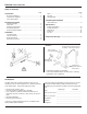
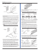
ENC 250™ MULTI-SECTION End of scale clearance requirements ... Mounting Information [1.0] 25mm Use this information to plan your Linear Encoder installation. • Mount the linear encoders close to machine guide ways to ensure system accuracy. • Space between reading head casting and mounting bracket or surface must not exceed [.188”] 4.7mm. [5.0] 127mm [5.0] 127mm • Minimum clearance is required above the scale case top. • A minimum clearance of [5.0] 127mm is required at each end of the scale case.
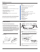
ENC 250™ MULTI-SECTION Scale Case Installation Procedure Mounting Requirements Left end section installation A variety of mounting conditions can be accommodated. Roll Pin • The machine configuration determines the brackets required to install the encoder. • Two typical mounting conditions are shown; reading head mounting plate, and a three piece combination assembly for mounting the reading head to the machine.
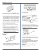
ENC 250™ MULTI-SECTION RTV This end first Center section(s) [1/4-20 x 1-1/4”] M6 x 30mm SHCS and washer • Apply RTV to the two sealant grooves in the right end on all three sides as done previously. Seal the seated ends of the spring pins, keeping the end and inside of the section free of sealant. • Slide the scale clip over the end of the scale section up to the stop in the scale case. • Clean off any excess RTV on the outside of the case.
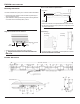
ENC 250™ MULTI-SECTION Suggested second location End to end distance must be xx40mm ± 2mm Suggested first location • Check for proper spacing between sections. Using a tape measure, record the over all length of the mounted scale sections (no end caps). Convert the length to millimeters by multiplying by 25.4. If the sections are mounted correctly, the last two digits of your measurement should be very close to 40 mm; (e.g. 6640 mm, 8040 mm, 10840 mm etc.).
ENC 250™ MULTI-SECTION Scale Tape Installation End view of tee slot • Apply a small amount of silicone grease – as a sealant - to the two M3 x 8mm FHSS. • Insert the screws through the scale case and thread into the anchor block. Tighten fasteners completely. Scale Tape Scale Tensioner • Place the Scale Tensioner into the tee slot on the left end of the scale case. • Retrieve the scale tape from the carton. The scale tape is shipped in a protective plastic coil. Do not uncoil the tape.
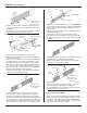
ENC 250™ MULTI-SECTION Approximately [1/8”] 3mm over hang Insert straight pins here to fasten ends of lip seals Straight pin If necessary pull the lip seal along at different points along the inserted length. Insert the 4 straight pins from the hardware kit into the ends of the lip seal grooves to keep the lip seals from pulling away from the ends of the scale case. Trim the lip seals ends with a pair of scissors so that there is an overhang of approximately [1/8”] 3mm at each end.
ENC 250™ MULTI-SECTION Installing the reading head • Move the axis so that the reading head is at the tape tensioning position indicated by the tension label on the right side of the scale. • Set the readout’s display and encoder resolution to .005 mm. See readout reference manual for setting resolution. The reading head must be mounted in the same location as it is held by the alignment brackets.
ENC 250™ MULTI-SECTION Trouble Shooting If you experience difficulties with your installation, do the following to determine the problem. Apply silicone grease to plug and reinsert it Checking the Readout Difficulties on more than one axis are usually associated with the readout. Follow these steps to determine if your difficulties are associated with the readout: • Ensure that the linear encoder connectors are correctly seated.
ENC 250™ MULTI-SECTION Mechanical Specifications Mechanical Specifications Digital Resolution 5µm [0.0002 in.] Grating pitch 100µm [0.00393 in] Scale medium Reflective Metal Tape Accuracy @ 20° C ± 15µm/M [0.00018 in/ft] Max. slew speed 1 M/sec [40 in/sec.] Force required to move reading head Operating Environment: Temperature Relative Humidity Storage Environment: Temperature Humidity Weight w/cable ± 3.3 Newtons [0.
ENC 250™ MULTI-SECTION Digital Differential Pin 1 Pin 2 Pin 3 Pin 4 Pin 5 Pin 6 Pin 7 Pin 8 Pin 9 N/C Green Yellow Blue Red White Brown Pink Gray N/C Channel A+ Channel A- Channel B+ Channel B- Ground Vcc, + 5.1 ± 0.1 VDC Channel R+ Channel R- 1 6 5 9 Hassle-Free Warranty Acu-Rite Companies Inc.