
Owner's manual

SETUP
MILLPWR
Operation Manual Page 7-7
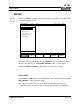
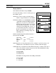
Error Compensation
If the milling machine shows signs of wear, actual part dimensions may differ from
programmed dimensions. A correction factor can be entered for the axis that is not
holding accurate dimensions.
If you know the error correction value in parts per million (PPM), you can type it in
directly. Otherwise, use the following procedure to find it for each axis:
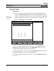
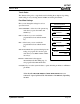
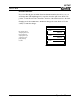
• Set up a standard gage block of
known length.
• Enter the standard length. If you need
to touch each end of the block, using
opposite edges of the probe or tool,
include the diameter of the tool in the
length of the standard. If you are using
the kind of gage where you use the
same edge of the tool for both ends,
just enter the block’s actual length.
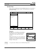
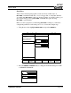
• Touch one end of the block and press
the FIRST POINT softkey.
• Touch the other end and press the SECOND POINT softkey.
• MILLPWR calculates and enters the correction in parts per million.
SERVO
OFF
FEED 0 100%
INCH
SCALE 1.0000TOOL:
FIRST
POINT
SECOND
POINT
CANCEL
CHANGES
ENTER LENGTH OF STANDARD. INCLUDE TOOL DIAMETER IF REQUIRED.
USE NEW
SETTINGS
SYSTEM SETUP
2 OF 4
ERROR COMPENSATION
X: STANDARD LENGTH (INCH)
0.0000
X: COMPENSATION PPM
0
Y: STANDARD LENGTH (INCH)
0.0000
Y: COMPENSATION PPM
0
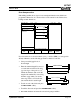
PROTECTION
ERROR COMPENSATION
ENCODER DIRECTION
SERIAL PORT
LENGTH OF STANDARD
LENGTH OF STANDARD
+ DIAMETER OF PROBE
LENGTH OF STANDARD
LENGTH OF STANDARD