Automatic Control Valves The Automatic Answer to Fluid Control watts.
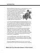
INTRODUCTION Specifying Automatic Control Valves is a critical balancing act. On one hand, you must have the utmost confidence not only in the quality and performance of the valve, but also in the knowledge and “hands-on” expertise of the manufacturer. On the other hand, product reliability must be unquestioned, meeting the exact design parameters specified. Orders must be shipped as promised, keeping your job on track, and after-the-sale support is essential.
TABLE OF CONTENTS Page Table of Contents . . . . . . . . . . . . . . . . . . . . . . . . . . . . . . . . .3 The More You Know . . . . . . . . . . . . . . . . . . . . . . . . . . . . . . .4 Competitive Cross Reference Chart . . . . . . . . . . . . . . . . . .5 Specifications . . . . . . . . . . . . . . . . . . . . . . . . . . . . . . . . . . .6 Float Control Valves ACV 110-10 Modulating Float . . . . . . . . . . . . . . . . . . . . . . . .7 ACV 110-14 On-Off/Adjustable Hi-Lo Level . . . . . . . . . . . . .
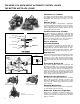
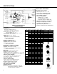
THE MORE YOU KNOW ABOUT AUTOMATIC CONTROL VALVES THE BETTER WATTS ACV LOOKS! Performance is standard The design and innovative features incorporated into every Watts Automatic Control Valve means consistent, dependable, high performance, positive control and long life. Efficient design The main valve, globe or angle pattern, is diaphragm actuated, hydraulically operated. It consists of only four major components.
COMPETITIVE CROSS-REFERENCE GUIDE Watts ACV Model No. Cla-Val Model No.
SPECIFICATIONS WATTS ACV FEATURES Standard Production Valves: * Wide range of sizes 1 1/4" - 24" * Fused epoxy coating 100% inside and out.
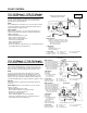
FLOAT CONTROL 110-10 (Globe) / 1110-10 (Angle) FLOAT CONTROL – MODULATING (CONSTANT LEVEL) ➡ CLOSES VALVE Flow Direction Shown: Under the Seat Optional ‘R’ Flow Over the Seat: ➪ OPENS VALVE The ACV 110-10 maintains a constant level in storage tanks and reservoirs. Valve controlled flow into the tank is proportional to discharge flow, keeping the tank full. NOTE: The modulating float control ACV 10-11, is remote mounted.
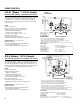
SOLENOID CONTROL 113-12 (Globe) / 1113-12 (Angle) ➡ CLOSES VALVE ➪ OPENS VALVE 1 4 SOLENOID ON/OFF (OPEN/CLOSE) Sizes 1 / " - 4" Operated by a 3-way solenoid, the main valve opens fully or closes drip-tight depending upon the actuation position of the solenoid, energized to open/energized to close. The valve may be remotely operated by timers, relays, probes or any triggered device to the solenoid. NOTE: Energized to open valve. Optional: energized to close valve.
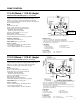
PUMP CONTROL 113-46 (Globe) / 1113-46 (Angle) BOOSTER PUMP CONTROL (Valves 4" and smaller) Solenoid operated pump control for controlled opening and closing on pump start-up and shut-down. Equipped with hydraulic check feature to close valve on pressure reversal and shut-off pump in event of pump failure. Valve and pump operations are interlocked by a limit switch assembly. NOTE: Energized to open valve. At time of order, advise factory actual system working pressure for correct solenoid selection.
PUMP CONTROL 413-21 (Globe) / 1413-21 (Angle) BOOSTER PUMP CONTROL / MECHANICAL LIFT CHECK Solenoid operated pump control for controlled opening and closing on pump start-up and shut-down. Equipped with mechanical liftcheck feature to close valve the moment flow stops, preventing reverse flow. Valve and pump operations are interlocked by a limit switch assembly. NOTE: Energized to open valve. At time of order, advise factory actual system working pressure for correct solenoid selection.
PUMP CONTROL 513-6 (Globe) / 1513-6 (Angle) DEEP WELL PUMP CONTROL The ACV 513-6 pump control valve starts in an open position during pump start-up, purging the deep well of air and debris to atmosphere. Controlled closing of the valve, opens the mainline check valve, gradually increasing line pressure. The valve reopens during shut-down cycle to gradually decrease line pressure and prevent shock. Valve and pump operations are interlocked by a limit switch assembly. NOTE: Energized to close valve. Max W.P.
RATE OF FLOW PRESSURE REDUCING 114R (Globe) / 1114R (Angle) RATE OF FLOW (“R” indicates over the seat flow) Maintains a constant flow rate, adjustable, regardless of fluctuations in line pressure. The rate of flow pilot senses the differential pressure across a thin edged orifice plate mounted in the valve inlet flange. It responds to changes in pressure and modulates the main valve to maintain the desired flow. SPECIFY: Desired flow rate at time of order.
PRESSURE REDUCING 115-2 (Globe) / 1115-2 (Angle) PRESSURE REDUCING / SUSTAINING Automatically reduces a higher inlet pressure to a constant lower outlet pressure regardless of changing flow rate and/or varying inlet pressure. Equipped with a pressure sustaining control which prevents the upstream pressure from dropping below a preset minimum.
PRESSURE REDUCING 115-4 (Globe) / 1115-4 (Angle) PRESSURE REDUCING / SOLENOID ON-OFF Automatically reduces a higher inlet pressure to a constant lower outlet pressure regardless of changing flow rate and/or varying inlet pressure. Equipped with a solenoid override feature allowing for electrical on-off operation of the valve. NOTE: Adjustment range: Standard: 20-175 psig Optional: 0-30 psig 100-300 psig (uses stainless steel control) Solenoid max W.P.
115-74 (Globe) / 1115-74 (Angle) PRESSURE REDUCING / LOW FLOW BY-PASS VALVE Automatically reduces a higher inlet pressure to a constant lower outlet pressure regardless of changing flow rate and/or varying inlet pressure. Equipped with a low flow by-pass feature which bypasses the main valve pressure function for low flow conditions.
PRESSURE RELIEF / SUSTAINING 116 (Globe) / 1116 (Angle) PRESSURE RELIEF / SUSTAINING Installed on a by-pass line, mainline pressure is accurately controlled by relief of excess pressure. Installed in a mainline it prevents upstream pressure from dropping below a preset minimum. NOTE: Adjustment range: Standard: 20-200 psig Optional: 0-30 psig 100-300 psig Additional relief/sustaining functions: - 116FM/1116FM (U.L. listed/F.M.
SURGE RELIEF / CHECK 116-52 (Globe) / 1116-52 (Angle) SURGE ANTICIPATOR RELIEF / REMOTE SENSE Used in pumping systems to protect equipment from damaging pressure surges or waves caused by rapid changes of flow within the pipeline. The 116-52 responds by opening at a preset low pressure setting, allowing for quick relief of the returning high pressure wave. The valve remains open as the integral accumulator is charged and then closes.
ALTITUDE 127-1 (Globe) / 1127-1 (Angle) ALTITUDE VALVE - ONE WAY FLOW (TANK FILL) Provides automatic filling of elevated tanks or reservoirs. When the altitude control senses a drop in level below the predetermined setpoint the valve opens to fill tank. Supply pressure is greater than static head pressure. Discharge of the tank is by a separate line. NOTE: Adjustment range: 5-20 FT. 10-75 FT. 50-200 FT.
FIRE PROTECTION VALVES 115F Globe / 1115F Angle PRESSURE REDUCING VALVE - UL LISTED The Watts ACV 115F (globe) and 1115F (angle) reducing valve meets all the requirements for UL Listed fire protection service. The Watts ACV valve goes “beyond the call of duty” by incorporating features to assure dependable, accurate control and long life.
FIRE PROTECTION VALVES 116FM (Globe) / 1116FM (Angle) FIRE PUMP RELIEF VALVE The Watts ACV 116FM (globe) and 1116FM (angle) relief valve meets all the requirements for UL Listed, FM approved fire protection service. The design and features incorporated into the Watts ACV valve assure accurate control, dependable performance and long life.
FIRE PROTECTION VALVES 100D-A Globe DELUGE VALVE/PNEUMATIC - HYDRAULIC - UL LISTED The Watts ACV 100D-A deluge valve meets all requirements for UL Listed, fire protection service. Valve opens on demand to provide water flow to the fire protection sprinkler system. Pilot system can be hydraulically, pneumatically or manually operated. Opening of valve is by loss of control pressure or by manual opening.
FIRE HYDRANT RELIEF VALVE 1116FH FIRE HYDRANT RELIEF VALVE VALVE DESCRIPTION Provides temporary relief protection to a water system by attaching directly to a fire hydrant via 2-1/2" FNST swivel on the inlet of the Watts 1116FH Relief Valve. VALVE APPLICATION In municipal & rural water systems, elevated storage tanks provide outlets for system pressure surges. When these elevated tanks are out of service for inspection / repairs an overpressurization of the water transmission lines could occur.
APPLICATIONS IN COMMERCIAL HIGH RISE - BUILDING 110-14 COOLING TOWER LABORATORY 1116 DENTIST 115 DRAIN APARTMENT 1116 HOSPITAL 115-7 LAUNDRY 1116 116-BYR KITCHEN 115 SERIES 110-14 115-3 STREET LEVEL BOOSTER PUMP HOLDING TANK FLOW DIRECTION CITY WATER 23
HIGH PRESSURE SAFETY SHUT-OFF/ DOWNSTREAM EXPANSION RELIEF VALVE 116-BYR / 6116-BYR To be piped to (Air Gap) Drain VALVE FUNCTION – Valve is fully open when inlet pressure is below shut-off control set point – Valve fully closes if inlet pressure exceeds shut-off control set point – Can be equipped with a limit switch for signalling an alarm COMPONENTS 1. Main Valve 2. BP30 Relief Control 3. Fixed Orifice 4.
WATTS ACV 113-6RFP FLOOD PROTECTION SHUTDOWN VALVE Watts ACV 113-6RFP 110 VAC Supply Main To Flow Switch Inlet Shut-off Valve Watts 909 2.5" - 10" First Check Second Check Relief Valve To Junction Box Floor PROBLEM Property damage due to relief valve discharge that can occur due to dirt and debris within the valve or a mechanical failure within the backflow prevention assembly.
Watts ACV Industrial Control Valves WATTS ACV FEATURES Standard Production Valves: ❘ Wide range of sizes 1-1/4" - 24" ❘ Fused epoxy coating 100% inside and out.
Watts Series 813 Irrigation ACV Valves Features: ★ ★ ★ ★ ★ ★ ★ ★ ★ ★ ★ ★ Competitively priced Sizes 11⁄4" through 6" Line Serviceable Compact assembly Full range of options Anticorrosive pilot systems Proven pilots, functions & design Top & bottom guided stem for better control Stainless steel braided flexible tubing is available Non edge seat design eliminates wire drawn on low flows Quick delivery through your local Watts distribution network Worldwide service from the largest valve manufacturer - WATTS
IRRIGATION CONTROL VALVES .
IRRIGATION CONTROL VALVES 29
ENGINEERING DATA / SIZING INSTALLATION RECOMMENDATIONS AND REQUIREMENTS VERTICAL INSTALLATIONS Avoid mounting valves 6" and larger in a vertical discharge position (valve stem horizontal or cover pointed sideways). If your installation requires this mounting position consult the factory or specify at time of order. ISOLATION SHUT-OFF VALVES Butterfly or similar type valves should be installed in the line upstream and downstream of the automatic control valve to allow for maintenance service.
VALVE SIZING found on the vertical axis. (Your maximum differential pressure will be the highest inlet pressure minus the desired outlet pressure, this is also known as the delta P.) To properly size an automatic control valve you need to know the following: • Highest and Lowest inlet pressures • Outlet pressure • Maximum flow requirements • Minimum flow requirements Step 5: From this point draw a horizontal line until you intersect with the line corresponding to the valve size as selected in step 3.
PRESSURE DROP INDEX - PRESSURE REDUCING VALVES Calculate the pressure difference by subtracting the desired outlet pressure from the maximum inlet pressure. Find the number on the pressure difference line and note the outlet pressure index number. This is the lowest outlet pressure setting allowed without failing into the cavitation zone. Design of the WATTS Automatic Control Valve minimizes potential valve damage that can be caused by cavitation. Avoid continued operation within the cavitation zone.
SUBMITTAL / SPECIFICATION AUTOMATIC CONTROL VALVE 8550 HANSEN RD, HOUSTON, TEXAS 77075 / PH 713-943-0688, FAX 713-944-9445 WATTS ACV REFERENCE # DATE FIGURE # PROJECT IDENTIFICATION ASSEMBLY # SIZE QUANTITY DESCRIPTION TECHNICAL COMPONENT MAIN VALVE BODY / COVER BODY PATTERN END CONNECTION SPECIFICATION ❏ DUCTILE IRON - ASTM A536 65-45-12 ❏ ANGLE ❏ GLOBE ❏ 150# FLANGED ANSI B16.1 (Max. W.P. 250psi) ❏ 300# FLANGED ANSI B16.1 (Max. W.P. 400psi) ❏ THREADED ANSI B 16.4 (Max. W.P.
RECOMMENDED SPARE PARTS LIST FOR MAIN VALVE & PILOT CONTROL SYSTEMS DATE FIGURE # VALVE SIZE PART # The following indicated components are used on the WATTS ACV assembly listed above. Normal servicing can be accomplished by installation of elastomer repair kits. Controls may be replaced or overhaul kits installed as operating conditions require. Main Valve Kits: All rubber components (diaphragm, seat seal, stem O-rings (6" and larger valves), BunaN material).
HOW TO ORDER To order the “right ACV” please provide the following: Refer to valve specifications beginning on page 6 and the selected ACV # for detail list of standards/options. ACV # SIZE Main Valve Material – Ductile Iron / Epoxy – Other Body Type – Globe – Angle End Connection – Threaded – Flanged 150# – Flanged 300# – Grooved Trim (Seat) – Brass (Standard) – Stainless Steel Elastomers – Buna-N (Standard) – Other Options or accessories as noted.
A Watts Water Technologies Company C-CACV 0310 USA: Tel: (713) 943-0688 • Fax: (713) 944-9445 • Watts.com Canada: Tel: (905) 332-4090 • Fax: (905) 332-7068 • Watts.ca Latin America: Tel: (52) 81-1001-8600 • Fax: (52) 81-8000-7091 • Watts.