
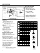
Specifications


7
110-10 (Globe) / 1110-10 (Angle)
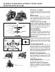
FLOAT CONTROL – MODULATING (CONSTANT LEVEL)
The ACV 110-10 maintains a constant level in storage tanks and
reservoirs. Valve controlled flow into the tank is proportional to
discharge flow, keeping the tank full.
NOTE:
The modulating float control ACV 10-11, is remote mounted. A still-
ing well around the float should be installed if the liquid surface is
subject to turbulence, ripples or wind.
QUICK SIZING:
Valve size same as fill line or one size smaller if discharge line is
smaller than fill. Match size/capacity to discharge requirements.
Points to consider:
– Minimum differential pressure 5 psig
– Refer to table for maximum flow
– Inlet pressure vs. tank head pressure
– Pressure drop at required flow
Refer to Engineering Data –
Pressure Drop Chart
– If valve size required is smaller than line size, consider ACV 6110-10.
Consult Watts ACV representative/factory
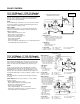
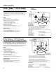
FLOAT CONTROL
VALVE FUNCTION
–
Maintains a constant liquid level in a tank.
– Remote mounted pilot is sensitive to slight
c
hanges in level and controls main valve:
Opens when level drops
Closes when level rises
C
OMPONENTS
1
. Main Valve
2. Modulating Float Control
3. Adj. Closing Speed
ACCESSORIES ❏ X - Isolation Cocks ❏ FC - Flo-Clean Strainer
Located as indicated ❏ Y -Y - Strainer ❏ L - Limit Switch
Included as marked ❏ P - Position Indicator
➡ CLOSES VALVE
➪ OPENS VALVE
Flow Direction Shown: Under the Seat
Optional ‘R’ Flow Over the Seat:
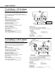
110-14 (Globe) / 1110-14 (Angle)
FLOAT CONTROL – ON/OFF (OPEN/CLOSE) ADJ. HI/LO LEVEL
The ACV 110-14 opens fully when the level reaches the preset low
point and shuts off drip tight when the high level is reached. The
rotary 3-port pilot is equipped with a vertical rod which allows the
float to rise and lower to the adjustable upper and lower stops.
NOTE:
The pilot is remote mounted unless specified valve mounted.
Standard equipped with brass rods and plastic float. Valve 2-6"
standard with 2-12" rods. Valves 8-16" standard with 4-12" rods.
Stainless steel rods and float are available. Provide a stilling well
around float if liquid surface is subject to turbulence, ripples or wind.
SPECIFY:
Valve mounted pilot is required, and valve discharge horizontal
or vertical.
QUICK SIZING: Valve size same as fill line or one size smaller.
Points to consider:
– Minimum differential pressure 5 psig
– Refer to Engineering Data – Flow Capacity Chart
– Inlet pressure vs. tank head pressure
– Pressure drop at required flow
Refer to Engineering Data – Pressure Drop Chart
– If valve size is smaller than line size, consider ACV 6110-14
Consult Watts ACV representative/factory
VALVE FUNCTION
– Valve opens when float reaches
lower level stop (adjustable)
– Valve closes when float reaches
upper level stop (adjustable)
– High and low level adjustments
allows for calculated draw down
Opens when level drops
Closes when levels rises
COMPONENTS
1. Main Valve
2. Float Pilot
3. Level Adjustment Stops
3A – Upper Level
3B – Lower Level
ACCESSORIES ❏ X - Isolation Cocks ❏ FC - Flo-Clean Strainer
Located as indicated ❏ Y -Y - Strainer ❏ L - Limit Switch
Included as marked ❏ P - Position Indicator
4" & Smaller
VALVE FUNCTION
– Valve opens when float reaches
lower level stop (adjustable)
– Valve closes when float reaches
upper level stop (adjustable)
– High and low level adjustments
allows for calculated draw down
Opens when level drops
Closes when levels rises
COMPONENTS
1. Main Valve
2. Float Pilot
3. Level Adjustment Stops
3A – Upper Level
3B – Lower Level
4. Accelerator
5. Adj. Closing Speed
6. Adj. Opening Speed
ACCESSORIES ❏ X - Isolation Cocks ❏ FC - Flo-Clean Strainer
Located as indicated ❏ Y -Y - Strainer ❏ L - Limit Switch
Included as marked ❏ P - Position Indicator
6" & Larger