
Product Manual

5 | P a g e © Adam Equipment Company 2010
3.3 SETTING
UP
THE
SCALES
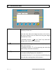
• Attach the power supply module to the connector on the side of the indicator.
Press the [On/Off] key. The software revision number will be displayed
followed by a self-test showing all digits before the zero is displayed along with
the unit of weight that was selected last.
3.4
CONNECTIONS
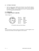
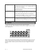
3.4.1 CONNECTION OF LOAD CELL
Please see figure 1
6: Pin +IN +Signal
7: Pin –IN -Signal
3: Pin AGND Shield
1: Pin +E, +Excitation
2: Pin +S +Sense
4: Pin –E -Excitation
5: Pin -S -Sense
As viewed from the back of the indicator
Note:
For 4 wire load cell, connect the load cell +Excitation and +Sense together at the
connector and -Excitation and -Sense together at the connector.
3
1
2
5
7
6
4