
Product Manual

6 | P a g e © Adam Equipment Company 2010
3
12
4
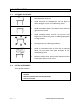
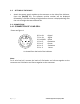
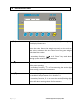
3.4.2 CONNECTION OF RS-232
RS-232 serial interface is a plug as figure 2 shows:
1: Pin GND, Signal Ground
2: Pin RXD, Received Data
3: Pin TXD, Transmitted Data
As viewed from the back of the indicator
See section 9 for details of the RS-232 Interface.
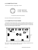
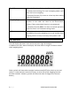
3.4.3 CONNECTION OF RELAY DRIVERS
The output to drive external relays is on the circuit board inside the enclosure. To
gain access you must remove the 6 screws securing the front to the rear of the case.
Pass the wires for the relays through the grommet on the rear panel. The wires will
connect to the PCB using the terminal strip P1.
ZERO
LOW
OK
HI
COM
SHIE
SEN+
EXE-
EXE+
SIG+
SIG-
SEN-
09/01/2009
AE9721 VER B
RXT
TXT
GND
BT1
C18
U5
U4
Q5
Power1
LC1
COM1
U1
P1
Relay Output
Common
High
OK
Low
Zero
RS-232 Interface
Load Cell Input
Power Connector
Battery Vin
+ - no polarity
Clock Battery
CR1220 type
The circuit to control the relays requires an external voltage compatible with the
relays used. For more information see section 10.