Adam Equipment HCB J Precious Metals and Density Balance (P.N. 308660002 Revision D1, June 2013) Software 4.
© Adam Equipment Company 2013
CONTENTS 1.0 INTRODUCTION .......................................................................................................2 2.0 SET UP ......................................................................................................................2 2.1 HCB J123, SETTING UP YOUR BALANCE .........................................................2 2.2 HCB J302, J1002 and J2002 SETTING UP YOUR BALANCE ............................6 2.3 PREPARING FOR USE................................................
1.0 INTRODUCTION Thank you for purchasing your new HCB J Precious Metals and Density Balance. As with our popular HighlandTM series of balances the HCB J has all the features you really need: DC adapter with internal rechargeable battery, HandiCalTM calibration, backlit display, and ShockProtectTM with overload indicator. With the RS-232 interface for communication with printers and computers, splash-proof keypad, and sturdy plastic construction, the HCB J will be a balance you can rely upon.
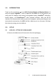
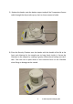
2) Remove the shipping protection screw and transit disc from the top of the balance 3) Place the Beaker Support assembly onto the top housing with the Temperature Sensor cable running down the back of the balance. 4) Lift the beaker away to the rear and locate the Density Chamber support into the receptacle with the arrow facing the rear of the balance. Press gently to insert it then secure the support in the center using the M4 x 20mm screw which is packed in the accessory bag.
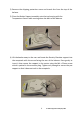
5) Replace the beaker onto the beaker support and pull the Temperature Sensor cable through the clip to take up any slack or loose amount of cable. 6) Place the Density Chamber over the beaker with the handle of the lid at the front and allowing for the sample pan to hang freely inside it. Secure the Chamber to the support by rotating it gently clockwise and locking into the 3 tabs. Take care not to push down or use excessive force on the Chamber when fixing as damage can be caused.
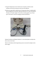
) Plug the Temperature sensor into the 5 pin connector, and the remote Indicator into the 6 pin connector at the rear of the balance. 8) Make sure again that the cable from the Temperature Sensor is tightly pulled down through the clip and that it does not interfere or sit close to the Density Chamber or Chamber support. If the cable is touching against any of these parts it will result in incorrect weighing and karat calculations.
2.
7 © Adam Equipment Company 2013
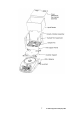
3) Remove the shipping protection screw and transit disc from the top of the balance. 4) Place the Chamber Support assembly onto the top housing. Press gently to insert it then secure the support in the center using the M4 x 20mm screw which is packed in the accessory bag. Tighten only enough to secure the pan support so that it does not rock in the receptacle.
5) Place the liquid chamber onto the support. Ensure the line marking the water level is to the front. 6) Place the temperature sensor onto the rear panel of the chamber. Pull the Temperature Sensor cable through the clip to take up any slack or loose amount of cable.
7) Position the sample pan in the beaker area and connect the 4 suspension wires to the rings in the support frame. 8) Plug the Temperature sensor into the 5 pin connector, and the remote Indicator into the 6 pin connector at the rear of the balance. 9) Make sure again that the cable from the Temperature Sensor is tightly pulled down through the clip and that it does not interfere or sit close to the Density Chamber or Chamber support.
When you are preparing to do a Density Test it will be necessary to fill the chamber with liquid. The choice of the type of liquid will be left for the user to decide, however some solvents may not be compatible with the Polycarbonate of the chamber or ABS of the Sample Pan. Test a small sample of the liquid on the plastics before filling the beaker if unsure. Fill the chamber with liquid lift the Chamber lid, or remove the Density Chamber from its support and pour through a funneled container.
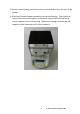
2.4 KEYPAD / DISPLAY FUNCTION The keypad and display have a number of features as shown and explained below: KEYS PRIMARY FUNCTION To turn the balance On or Off. SECONDARY FUNCTION ---- [On/Off] [Tare] Tares the balance and shows the net weight value. Pressing the [Tare] again will reset another tare value [Hold/Print] Will set the current weight to be held on the display and will also send the current weight data to the RS232 interface.
2.5 REAR PANEL The rear panel has connectors for the power, RS232, remote display and temperature sensor. For connections to these see the relevant sections. 2.6 INTERNAL RECHARGEABLE BATTERY The balance can be operated from the internal rechargeable battery or using an adapter. The battery life is approximately 24 hours with the backlight off. Depending on the usage of the backlight the lifetime of the battery will reduce and using the remote display will lessen the battery life considerably.
3.0 LOCATING AND PROTECTING YOUR BALANCE In order to keep your balance functioning at its best we suggest that you do the following: Avoid extremes of temperature. Do not place in direct sunlight or near air conditioning vents. Make sure the balance is located on a strong table and free from vibration. Avoid unstable power sources. Do not use near large users of electricity such as welding equipment or large motors. Do not let the balance battery go flat.
4.0 BASIC OPERATION 4.1 TURNING ON THE BALANCE Plug in the unit using the adapter or use the internal rechargeable battery. It is recommended that you charge the battery for at least 8 hours before first use. 1) To turn on press the [On/Off] key once and release. The balance will show the software revision and the battery voltage then self-test before showing the current temperature as measured or defined by the user.
5.0 DENSITY FUNCTION Once the HCB J is prepared for a density test and the parameters have been set for doing the Density Determination (see section 6) the following procedure is used to weigh the sample in air, and then again in water or another liquid, allowing you to determine the density of the sample and if applicable a determination of the purity (karat) of the gold in the sample. The Hold function must be enabled (see section 7.2) for the Density function to operate correctly.
display will show “HOLD”. If the Hold function is set to automatic you are not required to press the [Hold/Print] key once the weighing in liquid becomes stable. After the Hold symbol is shown press the [Air/Liquid] key to store this value. The Weight in Liquid indicator will be shown at which point the sample can be removed.
table below), the karat value and content value will not be displayed. An error message will be shown. Only the density value will be available. To return to normal weighing press the [Unit/Clr] key. To run another test ensure all weight is removed from the pan support in the water and from the Density Chamber. Gold Density values used for Karat determination for silver and copper alloys.
6.0 DENSITY PARAMETERS To use the density function it is necessary to set parameters describing the liquid used and the alloy being tested. These parameters can be set when the balance is in the normal weighing mode. 6.1 SELECTING THE ALLOY TO TEST The HCB J allows the alloy to be tested to be selected by the user. Select either Gold (Au), Platinum (Pt), Silver (Ag) or disable the alloy selection and show the weight only.
temperature of the water, selections are either using the automatic temperature sensor or to manually input the temperature. If another liquid is used then the user must set the density of that liquid. The display will show Liquid, Press [Tare] to enter this section. Press [Air/Liquid] or [Density] to select H2O or Define den. Press [Tare] to select the setting or press [Unit/Clr] to return to the Liquid display.
options are Silver (Ag), Copper (Cu), Silver: Copper in a 1:1 ratio (AG:CU 1-1), Silver: Copper in a user settable ratio (Ag:Cu: M-N) or a user defined density (Define den). When the display shows Alloy, press the [Tare] key to enter this section. The display will show the current setting for the alloy as above. Press the [air/Liquid] or [Density] key to change the display to another setting, then press [Tare] to select the setting.
When the sample is Platinum mixed with an alloy the user needs to select the option that describes the alloy used. If the alloy is Nickel (Ni), Palladium (PA) or Nickel plus Palladium in a 1:1 ratio (Ni:PA 1-1) select the option shown and press [Tare] to store the selection. The display will return to show Alloy. Press [Unit/Clr] to return to weighing or select the Liquid setting as above.
7.0 PARAMETERS The balance has 8 parameters that can be set by the user. FUNCTION F1 Unt SECTION See section 7.1 F2 HLd See section 7.2 F3 bL See section 7.
7.1 ENABLING WEIGHING UNITS, F1 UNT You can enable and disable the weighing units available to the user when they press the [Unit/Clr] key as described in section 4.4 Weighing Units. 1) Switch on the balance then press and hold the [Unit/Clr] key during the selfchecking test of the display. 2) After a few seconds, the display will show the first function F1 Unt. 3) When F1 Unt is displayed you can press the [Unit/Clr] key to return to normal weighing or press [Air/Liquid] to go to the next function.
The following table shows different units which are available to the user and the conversion factors for each. Name of the Description Units Grams A standard metric unit Carats Used for weighing jewelry and gems, etc. Grains A basic weighing unit in the imperial system. Used to weigh gun powder. Pennyweight Pennyweight was the weight of a silver penny in medieval England. Equals to 1/20th of an Ounce Troy. Ounce Troy Troy ounce- used for weighing gold, silver and in pharmacy. Ounce Avoirdupois ounce.
7.2 HOLD FUNCTION, F2 HLD The hold function may be set to automatic, manual or off by the user. If the hold function is disabled the density function will not work. If it is set to auto the balance will hold the weight display when it becomes stable. If it is set to manual the user must press the [Hold/Print] key to set the hold function. AU Hd Off Hd On Hd Sets the hold function to operate automatically when a weight is stable. Sets the hold function to off. The Density function will not operate.
7.3 BACKLIGHT, F3 bL The backlight may be enabled or disabled by the user. If the backlight is disabled the battery life will be greater. The following settings are available: AU bL On bL Off bL Sets the backlight to operate automatically when a weight is placed on the balance or a key is pressed. Sets the backlight to be on at all times. Sets the backlight to be off at all times. 1) Switch on the balance then press and hold the [Unit/Clr] key during the selfchecking test of the display.
5) The following options are available for setting the serial output functions: Mode Print Feature Auto Mod After density is tested it will automatically send data for the test results to the printer as shown in section 9. Set Mod After density is tested and during the time the results are displayed press [Hold/Print] to send the data to the printer. This allows the user to print only when they are ready. Pressing [Hold/Print] a second time will send the data again.
7.5 AUTO POWER OFF, F5 OFF OFF The auto power off function helps conserve power by automatically turning the balance off when it is not in use. The Auto power off time can be set by the user in minutes, or to not be in operation (OFF). 1) Switch on the balance then press and hold the [Unit/Clr] key during the selfchecking test of the display. 2) After a few seconds, the display will show the first function F1 UNT. 3) Keep pressing the [Air/Liquid] key until F5 OFF is displayed.
7.7 ADJUST THE VALUE OF THE INTERNAL MASS, F7 CA The internal mass value stored in memory can be adjusted if required. 1) Switch on the balance then press and hold the [Unit/Clr] key during the selfchecking test of the display. 2) After a few seconds, the display will show the first function F1 UNT. 3) Press the [Air/Liquid] key until F7 CA is displayed. 4) Press the [Tare] key to view the current setting. 5) The display will show the current value with the first digit flashing.
USER TECHNICAL PARAMETERS, F8 SEt 7.8 The balance has a number of technical parameters the user can adjust. Display Description Default Value Filter settings - 1 to 3 n FIL 1 FIL 1 will allow the display to update at it’s fastest The Automatic Re zero range - 1 to 7 n ZEO 4 ZEO 1 is the minimum A/Z range and 7 is the maximum Stability symbol range - 1 to 6 n STA 2 STA 1 is the smallest stability range and 6 is the largest.
8.0 USER CALIBRATION The Highland series of balances comes standard with HandiCalTM internal calibration to make calibrating the balance quick and easy. However you can also calibrate the balance using an external verification weight if needed. The HandiCal method is the default but if you would like to use external calibration then you must first enable this via the parameter (section 7.6 Selecting the Internal or External Calibration). Install the handle for the calibration as shown below.
External Calibration 1) Press and hold the [Air/Liquid] and [Density] keys at the same time and power on the balance. 2) Release both keys when the display shows unload. 3) Remove any weight from the pan assembly and press the [Tare] key when the stable sign is shown. 4) The display will show an acceptable mass that can be used to calibrate the unit. You can change this value by pressing the [Air/Liquid] key to match the calibration mass you may have.
9.0 SERIAL INTERFACE SPECIFICATIONS The balance comes equipped with an RS-232 Serial Interface. The connector is a DE-9P female fitting with the following connections. Pin 2 TXD Transmitted data Pin 3 RXD Received data Pin 5 GND Signal ground Data Format for the printout is described below. All lines end with a carriage return and a line feed , (0dH and 0aH in ASCII). Format Output: The lines will include a heading for each line then the value. A typical output when weighing is shown below.
Format for simple weight only output: + 1.00 g Input command format: The balance can be controlled with the following commands. The commands must be sent in upper case letters, i.e. “T” not “t”. T P A U D Will do a combined Zero /Tare function the same as pressing the [Tare] key. Will perform the same functions as pressing the [Hold/Print] key.
10.0 REMOTE DISPLAY The remote display plugs into the 6 pin circular connector on the rear of the balance. Turn the balance off. Insert the connector from the remote display into the circular connector on the rear of the balance. Turn the balance on. The remote display will now display the same information as the balance display. NOTE: Using the remote display will use more of the battery power. It is suggested that you should use the power supply whilst using the remote display. 11.
12.0 TROUBLE SHOOTING 12.1 ERROR MESSAGES If an error message is shown, repeat the step that caused the message. If the error message is still shown then contact your dealer for support. ERROR CODE Err 4 DESCRIPTION POSSIBLE CAUSES SOLUTIONS Initial Zero is greater than allowed (4% of maximum capacity) when power is turned on) Weight on the pan when turning on. Internal calibration weight is in the lowered position. Damaged load cell. Damaged Electronics. Err 5 Keyboard Error.
12.2 REPLACEMENT PARTS AND ACCESSORIES If you need to order any spare parts and accessories contact your supplier or Adam Equipment. A partial list of the more common items follows: Part Number 3.01.4.0.11014 7.00.0.0.0012 1.12.0.0.11156 6.00.0.0.2028 3.02.4.0.9160 3.02.4.0.9156 3.02.4.0.9157 3.02.4.0.9158 3.02.4.0.9159 3.08.0.0.2043 3.08.1.2.2045 3.08.1.2.2046 3.08.1.2.2047 3.08.1.2.2048 3.08.0.0.2044 3.08.1.2.2049 3.08.1.2.2050 3.08.0.0.2045 3.08.1.2.2044 3.09.4.0.
13.0 SPECIFICATIONS 13.1 TECHNICAL SPECIFICATIONS Model # Maximum Capacity Readability Repeatability (s.d.) Linearity ± Pan Units of Measure 13.2 HCB J123 HCB J302 HCB J1002 HCB J2002 120g 300g 1000g 2000g 0.001g 0.01g 0.01 g 0.01 g 0.002g 0.01g 0.02 g 0.02 g 0.003g 0.02g 0.03 g 0.03 g Special pan assembly for Density Determination 132mm / 5.2” 160 x 165mm / 6.3” x 6.
14.0 WARRANTY INFORMATION Adam Equipment offers Limited Warranty (Parts and Labour) for the components failed due to defects in materials or workmanship. Warranty starts from the date of delivery. During the warranty period, should any repairs be necessary, the purchaser must inform its supplier or Adam Equipment Company. The company or its authorised Technician reserves the right to repair or replace the components at any of its workshops depending on the severity of the problems.
Manufacturer’s Declaration of Conformity This product has been manufactured in accordance with the harmonised European standards, following the provisions of the below stated directives: Electro Magnetic Compatibility Directive 2004/108/EC Low Voltage Directive 2006/95/EC Adam Equipment Co. Maidstone Road, Kingston Milton Keynes, MK10 0BD United Kingdom FCC COMPLIANCE This equipment has been tested and found to comply with the limits for a Class A digital device, pursuant to Part 15 of the FCC Rules.
ADAM EQUIPMENT is an ISO 9001:2008 certified global company with more than 35 years experience in the production and sale of electronic weighing equipment. Adam products are predominantly designed for the Laboratory, Educational, Health and Fitness, retail and Industrial Segments.