8 0 0 . 2 3 2 . 7 3 2 9 ADAMS RITE POWER SUPPLY PS-LR S a n ta F e St r e e t , P o m o n a , C A 9 1 7 6 7 • 8 0 0 . 8 7 2 . 3 2 6 7 • F a x OWNERS MANUAL AND INSTALLATION INSTRUCTIONS Document Part Number 80-0180-247 Rev.(H) ECN 11117 2 6 0 A DA M S R I T E M A N U FA C T U R I N G C O . A D A M S R I T E P O W E R S U P P LY P A R T N U M B E R P S - L R 2 - October - 2007 Rev Date: 07/26/10 Need more information? Visit our website at: Page 1 of 10 www.adamsrite.
A D A M S R I T E P O W E R S U P P LY P A R T N U M B E R P S - L R 8 0 0 . 2 3 2 . 7 3 2 9 P o m o n a , St r e e t , F e S a n ta CONFIGURE THE ADAMS RITE POWER SUPPLY_______________________________3 1.1. STEP-1 – SET PRIMARY VOLTAGE ___________________________________________3 1.2. STEP 2 – SET OPERATION MODE ___________________________________________4 1.3. STEP 3 – SET HOLD TIMES _________________________________________________4 1.4.
A D A M S R I T E P O W E R S U P P LY P A R T N U M B E R P S - L R 8 0 0 . 2 3 2 . 7 3 2 9 An optional mode is available allowing both retraction timers to activate in response to closure of either switch. The Adams Rite Power Supply is listed as an Exit Device, Access Control System unit to UL305 and UL1012 requirements for power supplies and CAN / CSA - C22.2. Exit devices under the system control remain latched during a complete power failure but always allow free mechanical egress. 1.
A D A M S R I T E P O W E R S U P P LY P A R T N U M B E R P S - L R 8 0 0 . 2 3 2 . 7 3 2 9 DUAL INPUT Single Input – Sequential Operation (Factory Setting) Application: Control one opening Operation: Either input retracts Exit Device #1 immediately followed by Exit Device #2. Dual input – Independent Operation Application: Control two separate openings Operation: Input IN1 retracts Exit Device #1. Input IN2 retracts EXIT DEVICE #2. 1.3.
A D A M S R I T E P O W E R S U P P LY P A R T N U M B E R P S - L R 8 0 0 . 2 3 2 . 7 3 2 9 9 1 7 6 7 • 8 0 0 . 8 7 2 . 3 2 6 7 • F a x C A P o m o n a , CONNECT FIRE ALARM **Caution** USE OF THE ADAMS RITE POWER SUPPLY WITH FIRE DOORS REQUIRES THE SYSTEM TO BE UNDER THE CONTROL OF AN AUTOMATIC FIRE CONTROL ALARM SYSTEM The Adams Rite Power Supply is factory set to be used without a fire alarm interface.
A D A M S R I T E P O W E R S U P P LY P A R T N U M B E R P S - L R A DAMS R ITE P OWER S UPPLY THE ADAMS RITE POWER SUPPLY IS INTENDED FOR INDOOR USE ONLY . Install the Power Supply close to the door that will be operated. Securely fasten the Power Supply to the wall using the mounting holes located in the back of the metal enclosure. Mounting holes are ¼ inch in diameter. Box dimensions are 10” wide x 10” long x 4” high. 1.8.
A D A M S R I T E P O W E R S U P P LY P A R T N U M B E R P S - L R 8 0 0 . 2 3 2 . 7 3 2 9 9 1 7 6 7 • 8 0 0 . 8 7 2 . 3 2 6 7 • F a x C A P o m o n a , (OPTIONAL) This step is required to use the Adams Rite Power Supply with an automatic door opener. Automatic door opening systems need an indication of the latch state. The latch controller which is located in the panic device has relay contacts that let the automatic door opener know the latch state.
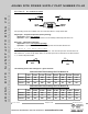
0 0 . 2 3 2 . 7 3 2 9 DESCRIPTIONS, PART NUMBERS, AND MEASUREMENTS 2.1. DESCRIPTIONS AND PART NUMBERS Two Wire Driver Board P/N# Solenoid P/N# Microswitch ( found on Solenoid ) P/N# PS-LR Board P/N# Battery Backup System Kit P/N# 31-0117-IP 31-0833-IP 31-0101 29-0623 BBK-LR Fuses for PS-LR Board (Can be purchased from Fuses Unlimited Ph # 1-800-255-1919) F1 - 4 Amps* P/N# 0213004.MXP F2 - 3.15 Amps* P/N# 02133.15P F3 - 7 Amps* (unserviceable) P/N# 0230007.HXP *All Slo Blo 2.2.
8 0 0 . 2 3 2 . 7 3 2 9 FREQUENTLY ASKED QUESTIONS / TROUBLESHOOTING 3.1. Q: THE EXIT DEVICE WON'T UNLOCK WHEN I USE MY ACCESS CONTROL SYSTEM? A: Check PS-LR board that MAIN POWER & OUTPUT POWER LEDs are on. Check SW2 switch (located next to TRANSFORMER connector J5). Setting should be on 120V. Disable Access Control from 1-2 of IN2 and/or 3-4 of IN1 found on J3 and place a jumper wire in 3-4 of IN1. If exit devices activate, problem could be the access controller.
A D A M S R I T E P O W E R S U P P LY P A R T N U M B E R P S - L R NEITHER 8 0 0 . 2 3 2 . 7 3 2 9 VERIFY CONNECTIONS • Ensure exit device wires are properly terminated in the power supply. • Verify continuity through power transfer devices such as wired hinges and door cords / loops. “MAIN • • • 9 1 7 6 7 • 8 0 0 . 8 7 2 . 3 2 6 7 • F a x “OUTPUT POWER” LED ON POWER SUPPLY BOARD IS NOT LIT • Check fuse F1. See Section 3.1 for replacement details.
A D A M S R I T E P O W E R S U P P LY P A R T N U M B E R P S - L R 8 0 0 . 2 3 2 . 7 3 2 9 9 1 7 6 7 • 8 0 0 . 8 7 2 . 3 2 6 7 • F a x C A P o m o n a , 4.1. Approved Replacement Fuses The Adams Rite Power Supply has two user serviceable fuses F1 and F2. These fuses are described below: F1 4 A/250V 5X20MM 226.5I8 SLOW-BLOW Fuse F1 is in line with the transformer output (28VDC) • Little Fuse P/N: 213004. MXP • Adams Rite Mfg P/N: 29-0667 F2 3.
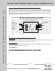
A D A M S R I T E P O W E R S U P P LY P A R T N U M B E R P S - L R 8 0 0 . 2 3 2 . 7 3 2 9 9 1 7 6 7 • 8 0 0 . 8 7 2 . 3 2 6 7 • F a x 4.2.2 Connector J3 – FIELD WIRING C A Connector Signal Descriptions 4.2.1 Connector J1 – BATTERY BACKUP 4.2.3 Connector J4 – MAIN POWER PIN 1 2 3 PIN DESCRIPTION Power In - 28VDC returned from battery charging system Power Out - 28VDC supplied to battery charging system Ground DESCRIPTION 1&2 INPUT #2: Normally open activation switch.