
Installation Instructions


ADAMS RITE MANUFACTURING CO.
ADAMS RITE POWER SUPPL
ADAMS RITE POWER SUPPL
Y
Y
P
P
ART NUMBER PS-LR
ART NUMBER PS-LR
260 Sant
260 Sant
a Fe S
a Fe S
treet, Pomona, CA
treet, Pomona, CA
91767•800.872.3267•Fax 800.232.7329
91767•800.872.3267•Fax 800.232.7329
Need more information? Visit our website at:
www
www
.adamsrite.com
.adamsrite.com
Page 10 of 10
Rev Date: 10/2/07
80-0180-247 REV (G)
3.5
NEITHER EXIT DEVICE RETRACTS AFTER THE CONTROL SWITCH IS ACTIVATED
.
V
ERIFY
CONNECTIONS
• Ensure exit device wires are properly terminated in the power supply.
• Verify continuity through power transfer devices such as wired hinges and door cords / loops.
“MAIN P
OWER” RED LED IS NOT LIT
• Verify line voltage is present.
• Check fuse F2 (in the black fuse holder). See Section 3.1 for replacement details.
• Ensure that the Primary Voltage Selection Switch SW2 is properly set. See installation Step 1 for
additional information.
“OUTPUT P
OWER” LED ON POWER SUPPLY BOARD IS NOT LIT
• Check fuse F1. See Section 3.1 for replacement details.
• If fuse F1 is blown, the wires that are run to the exit device are probably shorted together against
the conduit, door frame, or electric hinge. Use a meter to check for shorts.
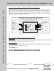
• There is no Fire Alarm connected between J3-9 and J3-10 or the factory installed jumper between
J3-9 and J3-10 is removed.
IN1 AND IN2 LIGHTS DO NOT LIGHT IN RESPONSE TO INPUT SWITCHES
• An open connection in the field wiring exists between the Adams Rite Power Supply and control
switch used for activating the latch solenoids.
• A defective control switch exists on J3 -1 and J3-2 or J3 -3 and J3-4.
OUT1 AND OUT2 LIGHTS DO LIGHT IN RESPONSE TO INPUT SWITCHES
• An open connection in the field wiring between the Adams Rite Power Supply and the exit device
may exist. Do a resistance check to verify.
If previous suggestions do not solve the problem, and one EXIT DEVICE works and one does not, prop
the door open and connect a voltmeter across the BLACK and WHITE leads coming from the exit device.
Next, activate the manfunctioning Exit Device. If the voltmeter measures approximately 28VDC at the time of
activation, but the latch did not budge, then two wire driver is not generating pulses to the PULL coil of the
solenoid. The exit device must be replaced.
3.6. DEVICES RETRACT EVEN THOUGH THE CONTROL SWITCH HAD NOT BEEN ACTIVATED.
• A maintained control switch is being used and is in the closed position.
• Control switch is defective – Disconnect switch to verify.
3.7 B
UZZING SOUND IS COMING FROM INSIDE THE EXIT DEVICE.
• The latch is binding against its corresponding strike and preventing it from retracting fully due to
misalignment between the latch and strike opening.