
Installation Instructions


ADAMS RITE POWER SUPPL
ADAMS RITE POWER SUPPL
Y
Y
P
P
ART NUMBER PS-LR
ART NUMBER PS-LR
Need more information? Visit our website at:
www
www
.adamsrite.com
.adamsrite.com
Page 12 of 10
Rev Date: 10/2/07
80-0180-247 REV (G)
ADAMS RITE MANUFACTURING CO.
260 Sant
260 Sant
a Fe S
a Fe S
treet, Pomona, CA
treet, Pomona, CA
91767•800.872.3267•Fax 800.232.7329
91767•800.872.3267•Fax 800.232.7329
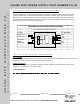
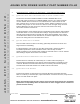
4.2
Connector Signal Descriptions
4.2.1 Connector J1 – BATTERY BACKUP
PIN DESCRIPTION
1 Power In - 28VDC returned from battery charging system
2 Power Out - 28VDC supplied to battery charging system
3 Ground
4.2.2 Connector J3 – FIELD WIRING
PIN DESCRIPTION
1&2
INPUT #2: Normally open activation switch.
3&4
INPUT #1: Normally open activation switch.
5
EXIT DEVICE #2, Coil return
6
EXIT DEVICE #2, +28VDC
7
EXIT DEVICE #1, Coil return
8
EXIT DEVICE #1, +28VDC
9
FIRE RELAY
10
FIRE RELAY
4.2.3 Connector J4 – MAIN POWER
L
The Main Power LIVE / HOT input.
Usually black or any other color other than white or Green
N
The Main Power NEUTRAL / RETURN input. White Conductor