
Installation Instructions


ADAMS RITE MANUFACTURING CO.
ADAMS RITE POWER SUPPL
ADAMS RITE POWER SUPPL
Y
Y
P
P
ART NUMBER PS-LR
ART NUMBER PS-LR
260 Sant
260 Sant
a Fe S
a Fe S
treet, Pomona, CA
treet, Pomona, CA
91767•800.872.3267•Fax 800.232.7329
91767•800.872.3267•Fax 800.232.7329
Need more information? Visit our website at:
www
www
.adamsrite.com
.adamsrite.com
Page 7 of 10
Rev Date: 10/2/07
80-0180-247 REV (G)
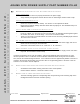
1.11. STEP 11 – WIRE AUTOMATIC DOOR INTERFACE (OPTIONAL)
This step is required to use the Adams Rite Power Supply with an automatic door opener. Automatic door
opening systems need an indication of the latch state. The latch controller which is located in the panic
device has relay contacts that let the automatic door opener know the latch state. The relay contacts are
closed when the latch is fully retracted. The relay contacts open when the latch is extended. Connect the
automatic door opener as shown in the figure below.
1.12.
STEP 12 –
WIRING PRIMARY POWER CONNECTION
J4 Connection
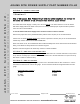
For the 115/230 VAC power input, terminal block J4 will accommodate up to 12AWG wire. Connect the mains
“live wire” to J4 pin L. Connect the mains neutral wire to J4 pin N.
Ground Connection
An earth ground connection is provided for, within the chassis. Make the ground connection to the green
ground screw located on the back of the chassis.
**Caution**
A
N EARTH GROUND CONNECTION MUST BE MADE TO THE CHASSIS
.
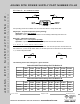
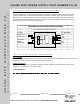
TWO WIRE DRIVER BOARD WIRING DIAGRAM
Two Wire Driver Board # 31-0117*
To PS-LR P/N:29-0310 TO SOLENOID
Output 1 & 2
Black
Output 3 & 4 PWR Re d
PWR White
AUTOMATIC
DOOR
RLY Blue
OPERATOR RLY Blue
* Found in Adams Rite LR Exit Device