
Installation Instructions


ADAMS RITE MANUFACTURING CO.
ADAMS RITE POWER SUPPL
ADAMS RITE POWER SUPPL
Y
Y
P
P
ART NUMBER PS-LR
ART NUMBER PS-LR
260 Sant
260 Sant
a Fe S
a Fe S
treet, Pomona, CA
treet, Pomona, CA
91767•800.872.3267•Fax 800.232.7329
91767•800.872.3267•Fax 800.232.7329
Need more information? Visit our website at:
www
www
.adamsrite.com
.adamsrite.com
Page 9 of 10
Rev Date: 10/2/07
80-0180-247 REV (G)
3. FREQUENTLY ASKED QUESTIONS / TROUBLESHOOTING
3.1. Q: THE EXIT DEVICE WON'T UNLOCK WHEN I USE MY ACCESS CONTROL SYSTEM?
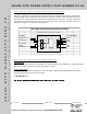
A: Check PS-LR board that MAIN POWER & OUTPUT POWER LEDs are on.
Check SW2 switch (located next to TRANSFORMER connector J5). Setting should be
on 120V. Disable Access Control from 1-2 of IN2 and/or 3-4 of IN1 found on J3 and
place a jumper wire in 3-4 of IN1. If exit devices activate, problem could be the access
controller. Verify Jumper on J3 9-10 for Fire Alarm is secure and tight. Verify connector
for BATT BACKUP is in place and secure. Also check for shorts in the wiring
and if fuses are blown in the PS-LR.
If existing hardware, check Solenoid for burnt and discolored tape. Measure Ohm readings
on Solenoid. Refer to 1.14 for solenoid value readings. Verify microswitch on solenoid is
normally closed. Switch becomes normally open when powered applied. Verify revision
on Two Wire Driver Board. If lower than REV H, recommend replacement. Also check for
shorts in the wiring and if fuses are blown in the PS-LR.
3.2. Q: I
HAVE BLOWN FUSES IN MY PS-LR
A: If new install. Check for shorts in the wiring, particularly around the exit device and
hinge. Check for rods binding.
If existing hardware, verify revision on Two Wire Driver Board. If lower than REV H.
recommend replacement. Check Solenoid for burnt or discolor tape. Possible
plunger is binding in core. Measure Ohm readings on Solenoid. Refer to 1.14 for solenoid
value readings. Replace PS-LR board if F3 is blown.
3.3. Q: T
HE EXIT DEVICE INTERMITTENTLY LOCKS AND UNLOCKS?
A: When device is activated, the solenoid may do a "chatter" where the plunger is
released and then pulled back by the solenoid. Check microswitch on solenoid for loose
terminals. Measure microswitch with Ohm Meter for continuity. Recommend replacing
Two Wire Driver board and Solenoid if no trouble found on microswitch.
3.4. Q: N
O POWER TO THE SOLENOID.
A: Check microswitch on solenoid for loose terminals. Measure microswitch with Ohm
Meter for continuity. If meaused open, replace Microswitch. If terminals are loose, crimp terminal
connec tors with needle nose pliers.
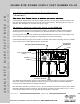
Before proceeding through the next section, ensure that exit device latches are not binding
against their corresponding strikes. A bound latch can cause sluggish electric retraction or
prevent retraction entirely.