
Specifications


ADC12D1800RF
SNAS518I –JULY 2011–REVISED JANUARY 2014
www.ti.com
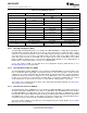
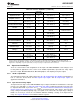
Table 6-1. Non-ECM Pin Summary
Pin Name Logic-Low Logic-High Floating
Dedicated Control Pins
DES
DES Non-DES Mode Not valid
Mode
Demux
NDM Non-Demux Mode Not valid
Mode
DDRPh 0° Mode 90° Mode Not valid
CAL See Calibration Pin (CAL) Not valid
CalDly Shorter delay Longer delay Not valid
Power Down Power Down
PDI I-channel active
I-channel I-channel
Power Down Power Down
PDQ Q-channel active
Q-channel Q-channel
TPM Non-Test Pattern Mode Test Pattern Mode Not valid
FSR Not allowed Nominal FS input Range Not valid
Dual-purpose Control Pins
V
CMO
AC-coupled operation Not allowed DC-coupled operation
Higher LVDS common-mode Lower LVDS common-mode
V
BG
Not allowed
voltage voltage
6.2.1.1 Dual Edge Sampling Pin (DES)
The Dual Edge Sampling (DES) Pin selects whether the ADC12D1800RF is in DES Mode (logic-high) or
Non-DES Mode (logic-low). DES Mode means that a single analog input is sampled by both I- and Q-
channels in a time-interleaved manner. One of the ADCs samples the input signal on the rising sampling
clock edge (duty cycle corrected); the other ADC samples the input signal on the falling sampling clock
edge (duty cycle corrected). In Non-ECM, only the I-input may be used for DES Mode, a.k.a. "DESI
Mode". In ECM, the Q-input may be selected via the DEQ Bit (Addr: 0h, Bit: 6), a.k.a. "DESQ Mode". In
ECM, both the I- and Q-inputs maybe selected, a.k.a. "DESIQ Mode".
To use this feature in ECM, use the DES bit in the Configuration Register (Addr: 0h; Bit: 7). See
DES/Non-DES Mode for more information.
6.2.1.2 Non-Demultiplexed Mode Pin (NDM)
The Non-Demultiplexed Mode (NDM) Pin selects whether the ADC12D1800RF is in Demux Mode (logic-
low) or Non-Demux Mode (logic-high). In Non-Demux Mode, the data from the input is produced at the
sampled rate at a single 12-bit output bus. In Demux Mode, the data from the input is produced at half the
sampled rate at twice the number of output buses. For Non-DES Mode, each I- or Q-channel will produce
its data on one or two buses for Non-Demux or Demux Mode, respectively. For DES Mode, the selected
channel will produce its data on two or four buses for Non-Demux or Demux Mode, respectively.
This feature is pin-controlled only and remains active during both Non-ECM and ECM. See Demux/Non-
demux Mode for more information.
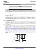
6.2.1.3 Dual Data Rate Phase Pin (DDRPh)
The Dual Data Rate Phase (DDRPh) Pin selects whether the ADC12D1800RF is in 0° Mode (logic-low) or
90° Mode (logic-high) for DDR Mode. If the device is in SDR Mode, then the DDRPh Pin selects whether
the ADC12D1800RF is in Falling Mode (logic low) or Rising Mode (logic high). For DDR Mode, the Data
may transition either with the DCLK transition (0° Mode) or halfway between DCLK transitions (90° Mode).
The DDRPh Pin selects 0° Mode or 90° Mode for both the I-channel: DI- and DId-to-DCLKI phase
relationship and for the Q-channel: DQ- and DQd-to-DCLKQ phase relationship.
To use this feature in ECM, use the DPS bit in the Configuration Register (Addr: 0h; Bit: 14). See SDR /
DDR Clock for more information.
42 Functional Description Copyright © 2011–2014, Texas Instruments Incorporated
Submit Documentation Feedback
Product Folder Links: ADC12D1800RF