
Specifications

ADC1XD1X00
V
IN
I+
50:
Source
V
IN
I-
1:1 Balun
C
couple
C
couple
100:
V
IN
Q+
V
IN
Q-
100:
C
couple
C
couple
ADC12D1800RF
www.ti.com
SNAS518I –JULY 2011–REVISED JANUARY 2014
6.4 Applications Information
6.4.1 THE ANALOG INPUTS
The ADC12D1800RF will continuously convert any signal which is present at the analog inputs, as long as
a CLK signal is also provided to the device. This section covers important aspects related to the analog
inputs including: acquiring the input, driving the ADC in DES Mode, the reference voltage and FSR, out-of-
range indication, AC/DC-coupled signals, and single-ended input signals.
6.4.1.1 Acquiring the Input
The Aperture Delay, t
AD
, is the amount of delay, measured from the sampling edge of the clock input, after
which the signal present at the input pin is sampled inside the device. Data is acquired at the rising edge
of CLK+ in Non-DES Mode and both the falling and rising edge of CLK+ in DES Mode. In Non-DES Mode,
the I- and Q-channels always sample data on the rising edge of CLK+. In DES Mode, i.e. DESI, DESQ,
DESIQ, and DESCLKIQ, the I-channel samples data on the rising edge of CLK+ and the Q-channel
samples data on the falling edge of CLK+. The digital equivalent of that data is available at the digital
outputs a constant number of sampling clock cycles later for the DI, DQ, DId and DQd output busses,
a.k.a. the latency, depending on the demultiplex mode which is selected. In addition to the latency, there is
a constant output delay, t
OD
, before the data is available at the outputs. See t
OD
in the Timing Diagrams.
See t
LAT
, t
AD
, and t
OD
in Converter Electrical Characteristics AC Electrical Characteristics.
6.4.1.2 Driving the ADC in DES Mode
The ADC12D1800RF can be configured as either a 2-channel, 1.8 GSPS device (Non-DES Mode) or a 1-
channel 3.6 GSPS device (DES Mode). When the device is configured in DES Mode, there is a choice for
with which input to drive the single-channel ADC. These are the 3 options:
DES – externally driving the I-channel input only. This is the default selection when the ADC is configured
in DES Mode. It may also be referred to as “DESI” for added clarity.
DESQ – externally driving the Q-channel input only.
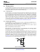
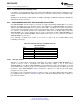
DESIQ, DESCLKIQ – externally driving both the I- and Q-channel inputs. VinI+ and VinQ+ should be
driven with the exact same signal. VinI- and VinQ- should be driven with the exact same signal, which is
the differential complement to the one driving VinI+ and VinQ+.
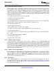
The input impedance for each I- and Q-input is 100Ω differential (or 50Ω single-ended), so the trace to
each VinI+, VinI-, VinQ+, and VinQ- should always be 50Ω single-ended. If a single I- or Q-input is being
driven, then that input will present a 100Ω differential load. For example, if a 50Ω single-ended source is
driving the ADC, then a 1:2 balun will transform the impedance to 100Ω differential. However, if the ADC
is being driven in DESIQ Mode, then the 100Ω differential impedance from the I-input will appear in
parallel with the Q-input for a composite load of 50Ω differential and a 1:1 balun would be appropriate.
See Figure 6-5 for an example circuit driving the ADC in DESIQ Mode. A recommended part selection is
using the Mini-Circuits TC1-1-13MA+ balun with Ccouple = 0.22µF.
Figure 6-5. Driving DESIQ Mode
Copyright © 2011–2014, Texas Instruments Incorporated Functional Description 55
Submit Documentation Feedback
Product Folder Links: ADC12D1800RF