ADCP-75-154 Issue 3 August 2006 ClearGain® Tower Mounted Amplifier System 900/1800 MHz User Manual 1379659 Rev A
ADCP-75-154 • Issue 3 • August 2006 • Preface COPYRIGHT © 2006, ADC Telecommunications, Inc. All Rights Reserved REVISION HISTORY ISSUE DATE REASON FOR CHANGE 1 06/2003 New publication 2 07/2004 Update drawings 3 08/2006 Add 900 MHz Fullband product LIST OF CHANGES The technical changes incorporated into this issue are listed below. PAGE IDENTIFIER All DESCRIPTION OF CHANGE Update drawings and add 900 MHz specfications.
ADCP-75-154 • Issue 3 • August 2006 • Preface TABLE OF CONTENTS Content Page ABOUT THIS MANUAL . . . . . . . . . . . . . . . . . . . . . . . . . . . . . . . . . . . . . . . . . . . . . . . . . . . . . . . . . . . . . . . . . . . . . . . . . v ADMONISHMENTS . . . . . . . . . . . . . . . . . . . . . . . . . . . . . . . . . . . . . . . . . . . . . . . . . . . . . . . . . . . . . . . . . . . . . . . . . . . v CERTIFICATION . . . . . . . . . . . . . . . . . . . . . . . . . . . . . . . . . . . . . . . . . . .
ADCP-75-154 • Issue 3 • August 2006 • Preface Blank Page iv © 2006, ADC Telecommunications, Inc.
ADCP-75-154 • Issue 3 • August 2006 • Preface ABOUT THIS MANUAL This document describes the ADC ClearGain 900/1800 MHz tower mounted amplifier system and provides complete instructions for installing this product on a communications tower. ADMONISHMENTS Important safety admonishments are used throughout this manual to warn of possible hazards to persons or equipment. An admonishment identifies a possible hazard and then explains what may happen if the hazard is not avoided.
ADCP-75-154 • Issue 3 • August 2006 • Preface Blank Page vi © 2006, ADC Telecommunications, Inc.
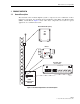
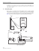
ADCP-75-154 • Issue 3 • August 2006 1 1.1 PRODUCT OVERVIEW General Description The ClearGain tower mounted amplifier system is composed of some combination of three functional components: the ClearGain Power Distribution Unit (PDU), the Masthead Unit (MHU), and the Bias-T. Figure 1 shows where these components are located in a typical application on a communications tower.
ADCP-75-154 • Issue 3 • August 2006 The MHU may be any of the three types shown. One PDU may support multiple MHUs of the same frequency. Each MHU requires one Bias-T. The ClearGain system also includes power cables and alarm cables. 1.2 Functional Description The basic purpose of a ClearGain tower mounted amplifier system is to amplify the uplink signal just after the antenna.
ADCP-75-154 • Issue 3 • August 2006 • The MHU—located on top of the tower, performs the amplifier function on the uplink signal. Two subcomponents of the MHU, an RF filter and a Low Noise Amplifier (LNA), are involved in the amplifier function. The downlink signal is not amplified. • The PDU—located in the base station, provides DC current for use in the amplifier function. The PDU outputs the DC current through a front port from which it travels by way of a short linkage cable to the Bias-T.
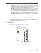
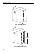
ADCP-75-154 • Issue 3 • August 2006 248 MILLIMETERS Clea rGai n 332 MILLIMETERS 900 BTS D ual Duple x 2-P ort T MA ANT 83 MILLIMETERS 21488-A Figure 4. 900 Fullband MHU Dimensions 196 MILLIMETERS Clea rGai n 260 MILLIMETERS BTS 1800 Dual Duple x 2-P ort T MA ANT 63 MILLIMETERS 18791-A Figure 5. 1800 Narrow Band MHU Dimensions Page 4 © 2006, ADC Telecommunications, Inc.
ADCP-75-154 • Issue 3 • August 2006 2 SYSTEM INSTALLATION 2.1 Installation Overview Installation consists of three main steps: 1. Installing the MHU: mechanical attachment, coaxial cables, ground cable. 2. Installing the Bias-T: mechanical attachment, coaxial cables, power cable. 3. Installing the PDU: mechanical attachment, operation power, and alarms. 2.2 Installing the Masthead Unit U-bolts are provided for mounting the MHU. Figure 6 provides an exploded view.
ADCP-75-154 • Issue 3 • August 2006 2.2.1 Installation of the MHU on the Mast Note: All hardware is specified in metric units. Before any installation, check that the ClearGain MHU has no visible damages or defects. Note: The ClearGain MHU must always be installed so that the connectors point downward. Not more than a 45-degree installation angle is recommended. 1. Place the MHU so that the bracket can be attached to the unit. Note: The threads are sensitive to damage. 2.
ADCP-75-154 • Issue 3 • August 2006 2.2.3 Installing Coaxial Cables Caution: Before connecting any coaxial cables, ensure that the BTS transmitter output is turned off and that precautions are taken to ensure that the transmitter cannot be activated during the equipment installation. Two short coaxial jumpers should be pre-made. One will connect the BTS port to the hardline and the other will connect the ANT port to the antenna.
ADCP-75-154 • Issue 3 • August 2006 Pow er D istrib ution Unit + – INPU T NO CO M N ALAR C FAIL M M DISC HU ONN ECT O MHU K 1 O MHU K 2 O MHU K 3 O MHU K 4 16772-A OK MHU 5 MHU OK 6 Figure 7. Example of PDU Standard Wall Mount 2.3.1.3 Rack Mount A mounting bracket, shown in Figure 8, is available that will allow the PDU to be mounted on a19-inch rack. If mounting the PDU on a rack, refer to the installation drawing provided with the mounting bracket.
ADCP-75-154 • Issue 3 • August 2006 2.3.2 Installation of PDU Cables There are three PDU cables: the ground cable, the alarm cable, and the power cable. Figure 9 shows the cable terminations on the front of the PDU. Connect the cables as follows: Figure 9. Cable Terminations on Front of PDU (Left to Right: Power Cable, Alarm Cable, Three MHU Cables, Ground Cable) 1. Connect the ground cable under the grounding screw on the PDU front panel. Connect the other end of the cable to the site grounding pole.
ADCP-75-154 • Issue 3 • August 2006 POWER DISTRIBUTION UNIT ALARM RELAY PDU ALARM LOGIC DC INPUT OUTPUTS 16773-A NO (NORMALLY OPEN) COM (COMMON) NC (NORMALLY CLOSED) Figure 10. PDU Alarm Logic 2.3.3 Setting the DIP Switch on the PDU The PDU has a DIP switch to disconnect unused MHU outputs (see Figure 11). For the MHU outputs that are used, the DIP switch must be in the “down” position. Unused outputs must be disconnected by setting the DIP switch to “ON”. Figure 11.
ADCP-75-154 • Issue 3 • August 2006 2.4 Bias-T Installation 2.4.1 Mechanical Attachment and Cable Connections Caution: Prior to installing any Bias-T unit, ensure that the BTS transmitter output is turned off and that precautions are taken to ensure that the transmitter cannot be activated during the equipment installation. The BIAS-T is designed to fasten directly into BTS coax-connector or directly to the feeder cable. Integrated lightening protection is built into each Bias-T unit.
ADCP-75-154 • Issue 3 • August 2006 2. Every output has a green LED, and it must be on if the output is used. Check that all the green LED’s on the used outputs are on. 3. If one of the used outputs has a LED off, there is something wrong with the PDU, Bias-T, MHU, or the feeder cable. 4. Disconnect the mini coaxial cable from the PDU and measure from the connector, that the PDU feeds 12VDC to the Bias-T. Do this measurement using a multimeter (Voltage measurement, DC).
ADCP-75-154 • Issue 3 • August 2006 ORIENT THE TMA SO THE RF CONNECTORS POINT TOWARDS THE GROUND. FEEDLINE JUMPER HARD LINE ANTENNA JUMPER COMMON FAILURE POINTS ARE THE ANTENNA AND FEEDLINE JUMPERS/CONNECTIONS. IF A SURGE PROTECTOR IS ANYWHERE IN BETWEEN THE BIAS-T AND THE TMA IT MUST BE ABLE TO PASS DC. CHECK IF EXTERNAL JUMPERS OR SURGE PROTECTORS PRESENT. SHELTER HARD LINE TEST POINT Figure 13. Tower Mounted Amplifiers Page 13 © 2006, ADC Telecommunications, Inc.
ADCP-75-154 • Issue 3 • August 2006 4.1 Troubleshooting 1. Observe and record PDU LED status. Disable or disconnect RF from BTS. Remove any surge protectors. Disconnect Bias-T from the antenna feedline/hardline/jumper/protector. HARD LINE SURGE PROTECTOR PDU 2. Multimeter checks: a. Measure voltage on the Bias-T _______ VDC. Normal is 13VDC. PDU b. Measure resistance of the feedline _______ Ohms. Normal is High or Very high Ω (KΩ/ΜΩ). HARD LINE 3. Antenna/cable analyzer checks.
ADCP-75-154 • Issue 3 • August 2006 HARD LINE PDU PDU DC supply (18-56 VDC with 5A fuse/breaker). 5. Re-connect to original configuration and return to service. PDU should illuminate a green LED for each active TMA if there are no faults in the system. 6. Check with operators for improved performance. 4.2 Troubleshooting Hints • • • • If voltage is outside of the normal range, trace it back towards the fault. If no resistance or low resistance, check protector, feedline, jumpers and TMA.
ADCP-75-154 • Issue 3 • August 2006 5 5.1 MHU SPECIFICATIONS DD900 Narrow Band Masthead Unit Table 1 provides typical specifications for the DD900 Full Band Masthead Unit. Table 1. DD900 Narrow Band Masthead Unit CATEGORY ELECTRICAL FILTER POWER HANDLING POWER PHYSICAL ENVIRONMENTAL QUALITY Page 16 © 2006, ADC Telecommunications, Inc.
ADCP-75-154 • Issue 3 • August 2006 5.2 DD900 Full Band Masthead Unit Table 2 provides typical specifications for the DD900 Masthead Unit. Table 2. DD900 Full Band Masthead Unit CATEGORY PARAMETER SPECIFICATION ELECTRICAL Nominal impedance of RF input and outputs 50 Ohm Frequency Range TX 925–960 MHz RX 880–915 Mhz Duplex Filter Bandwidth 35 MHz Passband (RX) Gain 12 dB Noise Figure 1.
ADCP-75-154 • Issue 3 • August 2006 5.3 DD1800 Masthead Unit Table 3 provides typical specifications for the DD1800 Masthead Unit. Table 3. DD1800 Narrow Band Masthead Unit CATEGORY PARAMETER SPECIFICATION FILTERS RX (up link) frequency range 1710–1755, 1720–1765, or 1740–1785 MHz TX (down link) frequency range 1805–1850, 1815–1860, or 1835–1880 MHz Insertion Losses 1800 Tx 0.2 dB UMTS Rx and Tx 0.2 dB 900 Rx and Tx 0.
ADCP-75-154 • Issue 3 • August 2006 6 CUSTOMER INFORMATION AND ASSISTANCE PHONE: U.S.A.