
User manual


ADCP-75-154 • Issue 3 • August 2006
Page 3
© 2006, ADC Telecommunications, Inc.
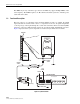
• The MHU—located on top of the tower, performs the amplifier function on the uplink
signal. Two subcomponents of the MHU, an RF filter and a Low Noise Amplifier (LNA),
are involved in the amplifier function. The downlink signal is not amplified.
• The PDU—located in the base station, provides DC current for use in the amplifier
function. The PDU outputs the DC current through a front port from which it travels by
way of a short linkage cable to the Bias-T. The injection of the DC current onto the coaxial
cable will not cause interference with signal transmission.
The PDU also monitors the status of all MHUs simultaneously by sensing their current
draws. If any of the MHUs fails, or if there is a cut or short circuit in the coaxial cable, the
PDU gives an alarm to the BTS. The PDU thus also monitors the condition of the coaxial
cable, not just the MHU. The PDU also has built-in lightning protection.
• The Bias-T—located on the coaxial cable, is a passive device that physically injects the
DC current onto the coaxial cable. The Bias-T injects the current into the center pin of the
coaxial cable.
A single PDU supports multiple MHUs (with one Bias-T required for each MHU). The number
of filters/LNAs supported depends on the system type.
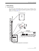
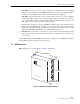
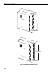
1.3 MHU Dimensions
MHU dimensions are shown in Figure 3, Figure 4, and Figure 5.
Figure 3. 900 Narrow Band MHU Dimensions
BT
S
AN
T
ClearGain
18790-A
63 MILLIMETERS
280 MILLIMETERS
250 MILLIMETERS
900 Dual Duplex 2-Port TMA