ADCP-80-526 Issue 6 December 2006 PowerWorx® Power Distribution Products Select Series™ Fuse Platform User Manual 18858-A 1354430 Rev B
ADCP-80-526 • Issue 6 • December 2006 • Preface COPYRIGHT © 2006, ADC Telecommunications, Inc. All Rights Reserved Printed in the U.S.A. REVISION HISTORY ISSUE DATE 1 12/1999 REASON FOR CHANGE Original. 2 02/2001 Changed cable management bar, updated cooling and temperature requirements. 3 07/2003 Updated for new two-hole compression lugs and plastic covers. 4 07/2004 Added warning statement saying use of one bus only of dual bus panel results in false alarms.
ADCP-80-526 • Issue 6 • December 2006 • Preface TABLE OF CONTENTS Content Page About This Manual . . . . . . . . . . . . . . . . . . . . . . . . . . . . . . . . . . . . . . . . . . . . . . . . . . . . . . . . . . . . . . . . . . . . . . . . . . . v Standards Certification . . . . . . . . . . . . . . . . . . . . . . . . . . . . . . . . . . . . . . . . . . . . . . . . . . . . . . . . . . . . . . . . . . . . . . . . v Admonishments . . . . . . . . . . . . . . . . . . . . . . . . . . . . . . . . . . . . . .
ADCP-80-526 • Issue 6 • December 2006 • Preface TABLE OF CONTENTS Content Page 4.6 Connecting Input Power . . . . . . . . . . . . . . . . . . . . . . . . . . . . . . . . . . . . . . . . . . . . . . . . . . . . . . . . . . . . 23 4.7 Installing Protective Covers . . . . . . . . . . . . . . . . . . . . . . . . . . . . . . . . . . . . . . . . . . . . . . . . . . . . . . . . . 25 4.8 Installing GMT Fuse Designation Pins . . . . . . . . . . . . . . . . . . . . . . . . . . . . . . . . . . . . . . . . . .
ADCP-80-526 • Issue 6 • December 2006 • Preface ABOUT THIS MANUAL This manual describes the PowerWorx® Select Series™ Fuse Platform and provides installation, operation, maintenance, and testing procedures. The Select Series™ Fuse Platform is available with various types of fuses including TPA, KLM, and GMT fuses. Two types of fuses can be combined within the same platform, if required.
ADCP-80-526 • Issue 6 • December 2006 • Preface Warning: Wet conditions increase the potential for receiving an electrical shock when installing or using electrically-powered equipment. To prevent electrical shock, never install or use electrical equipment in a wet location or during a lightning storm. Page vi © 2006, ADC Telecommunications, Inc.
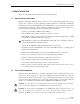
ADCP-80-526 • Issue 6 • December 2006 1 PRODUCT DESCRIPTION This section describes the PowerWorx Select Series Fuse Platform. 1.1 Product Functions and Features The Select Series Fuse Platform, shown on the front cover of this manual, supplies protected dc power to the –24 Vdc or –48 Vdc equipment typically installed in a central office, multimedia headend, remote site, Controlled Environmental Vault (CEV), or other restricted locations.
ADCP-80-526 • Issue 6 • December 2006 UL/CSA/CE LABEL BUS A POWER ON INDICATOR BUS B POWER ON (GREEN LED) INDICATOR (GREEN LED) BUS A BUS A KLM/KTK KLM/KTK FUSE HOLDERS FUSE ALARM INDICATOR (RED LED) (TYPICAL) BUS A GMT FUSE ALARM INDICATOR (RED LED) BUS A GMT FUSE HOLDER (4 POSITION) BUS B GMT FUSE ALARM INDICATOR (RED LED) BUS B KLM/KTK FUSE ALARM BUS B KLM/KTK INDICATOR (RED LED) FUSE HOLDER (TYPICAL) BUS B GMT FUSE HOLDER (4 POSITION) FRONT VIEW DESIGNATION CARD AND CARD HOLDER CHASSIS GROUND
ADCP-80-526 • Issue 6 • December 2006 Warning: If a KLM fuse holder without a fuse is connected to a load, an alarm is reported (alarm red LED lights and alarm contacts change states, as in a fuse failure). Depending on customer order, the fuse platform may have one fuse type alone, or GMT fuses in combination with one other fuse type (KLM or TPA).
ADCP-80-526 • Issue 6 • December 2006 • Rear protective input terminal covers and output terminal covers—Used to prevent accidental contact with the power input and output terminals. The number of covers provided depends on the fuse configuration. • Designation card and card holder—Used to record information about the protected equipment. The card holder has a pressure-sensitive adhesive backing to permit attachment to the panel, the rack, or a location close to the panel.
ADCP-80-526 • Issue 6 • December 2006 1.5 Accessories The following accessories are available for the fuse platform: • Standard size GMT, KLM, and TPA type fuses • GMT colored fuse-value designation pins (rivets) • Cable management bar kits • GMT fuse pullers • Two-hole compression connector lugs for input power connections • Lug terminals to connect #10 AWG wire to earth ground • GMT fuse value designation pin holders • Fuse value designation card holder kits 1.
ADCP-80-526 • Issue 6 • December 2006 For other types of fuses (TPA and GMT), if a fuse holder without a fuse is connected to a load, the corresponding sensor remains inactive and no failure is indicated. The maximum current capacity of each power bus circuit is 100 Amps. The total output current capacity of the fuses on each bus must, therefore, not exceed 100 Amps. The maximum current rating is marked on the fuse platform rear side.
ADCP-80-526 • Issue 6 • December 2006 1.8 Bus Capacity The current capacity of each power bus is 100 Amps maximum, which is marked above the input connectors on the rear of the fuse platform. The total current of a fuse platform with two buses is 200 Amps maximum.
ADCP-80-526 • Issue 6 • December 2006 1.11 Output Power Connectors Depending on the fuse configuration used, the fuse platform will have at least one, and up to four, output power terminal blocks, located on the rear side of the platform. The number present will depend on the fuse type and number of fuse positions. In general, there will be one terminal block per bus for each fuse type present on that bus. All of the output power terminal blocks are screw-down barrier terminal strips.
ADCP-80-526 • Issue 6 • December 2006 The alarm circuitry uses form C alarm relay dry contacts. During normal operation (power applied and all fuses operational), the normally open (NO) contacts remain open and the normally closed (NC) contacts remain closed. When a fuse fails on either bus or power to either is lost, the NO contacts close creating a connection from NO and common and the normally closed (NC) contacts open creating an open circuit between NC and common.
ADCP-80-526 • Issue 6 • December 2006 Note: If a KLM or KTM fuse holder without a fuse is connected to a load, this situation causes the red LED to light and the alarm contacts to change states, same as would occur in a fuse failure. For other types of fuses (TPA and GMT), if a fuse holder without a fuse is connected to a load, the corresponding sensor remains inactive and no failure is indicated. 1.
ADCP-80-526 • Issue 6 • December 2006 0.38 IN. (0.96 CM) 14228-A 1.00 IN. (2.54 CM) Figure 5. Voltage Designation Label 1.19 Environmental Characteristics Table 2 lists the environmental characteristics of the fuse platform. Table 2. Fuse Platform Environmental Characteristics PARAMETER DESCRIPTION Operating temperature –5° C to +50° C Storage temperature –45° C to +85° C Humidity range (operating) 0% to 95% humidity (non-condensing) Altitude range –197 ft. (0.06 km) to 13,000 ft. (3.
ADCP-80-526 • Issue 6 • December 2006 1.23 Protective Cover A smoked plastic protective cover is mounted over the input power connectors, the output power connectors, the chassis ground terminals, and the external alarm contact connections. To access the connectors and terminals, loosen (do not remove) the four screws. 1.24 Dimensions Figure 6 shows the dimensions of the fuse platform. 17.13 IN. (43.51 CM) 11.1 IN. (28.2 CM) 10.00 IN. (25.41 CM) 1.75 IN. (4.44 CM) 23.00 IN. (58.42 CM) 22.31 IN. (56.
ADCP-80-526 • Issue 6 • December 2006 2 UNPACKING AND INSPECTION Before starting the installation, always open the shipping boxes and verify that all parts have been received and that no shipping damage has occurred. Use the following procedure to unpack and inspect the fuse platform: 1. Open the shipping carton and carefully unpack the fuse platform from the protective packaging. 2. Check the panel for broken or missing parts.
ADCP-80-526 • Issue 6 • December 2006 3.3 Materials Required The following materials are required to install the fuse platform: • • • • • • #2 AWG insulated copper wire for input power wires 2-hole compression lugs for #2 AWG wire (0.
ADCP-80-526 • Issue 6 • December 2006 3. Re-install the fuse holder (with working fuse). 4. Connect one test probe to the BATT (–) terminal on the input power terminal block. 5. Connect the other test probe to the BATT terminal on the output power terminal block. 6. Verify that continuity exists between the specified terminals. 7. Repeat the test procedure for the second fuse type, if present. 8. Repeat the test procedure for the second power bus, if present.
ADCP-80-526 • Issue 6 • December 2006 4. Repeat the test procedure for second fuse type, if present. 5. Repeat the test procedure for the second power bus, if present. TEST 4- POWER BUS B: VERIFY THAT CONTINUITY EXISTS BETWEEN INPUT AND TYPE 1 FUSED OUTPUT RTN TERMINALS TEST 4- POWER BUS A: VERIFY THAT CONTINUITY EXISTS BETWEEN INPUT AND TYPE 1 FUSED OUTPUT RTN TERMINALS 18874-A Figure 10.
ADCP-80-526 • Issue 6 • December 2006 Caution: This equipment employs electrical voltage and amperage levels which may be considered an electrical hazard. Care should be exercised to assure that only qualified personnel are allowed to install, operate, maintain, or otherwise come in contact with this equipment when the fuse platform is energized. Only insulated tools should be used on energized elements of the fuse platform.
ADCP-80-526 • Issue 6 • December 2006 4.2 Mounting Fuse Platform on Rack The fuse platform can be mounted in either a 19- or 23-inch (48.26 or 58.42 cm) wide rack. Two sets of mounting brackets, one set for 19-inch racks and one set for 23-inch racks, are provided with the fuse platform. Eight 5/16-inch (7.936 mm) long, thread-forming, Phillips-drive, 8-32 flat-head screws are provided for attaching the mounting brackets to the panel. Four 3/8-inch (9.
ADCP-80-526 • Issue 6 • December 2006 4. Place the fuse platform in the specified mounting space within the rack. 5. Secure the fuse platform to the equipment rack as shown in Figure 14 using the four 3/8inch (9.53 mm) long pan-head screws and flat washers provided. Caution: Do not use any hardware other than the hardware supplied with the fuse platform. TIGHTEN MOUNTING SCREWS TO 27 POUND-FORCE INCHES (3.
ADCP-80-526 • Issue 6 • December 2006 3. Locate the C GND (chassis ground) studs at the rear of the panel as shown in Figure 15. DETAIL DRAWING OF GROUNDING WIRE CONNECTION 18868-A TIGHTEN STUD NUT TO 23 POUND-FORCE INCHES (2.6 NEWTON METERS) OF TORQUE Figure 15. Chassis Ground Connections 4. Connect the ring terminal end of each wire to one of the studs and secure using the nuts with captive star washers provided (requires 3/8-inch socket). Tighten each stud nut to 23 pound-force inches (2.
ADCP-80-526 • Issue 6 • December 2006 4.4 Connecting Alarms Depending on the model being installed, the fuse platform will have either of two types of alarm connectors on the rear side of the platform: • Screw-down barrier terminal strip • Wire wrap pin Figure 16 shows the two types. Connect the connectors as follows: • Screw-down barrier terminal strip: The terminal screw size is 3-48. Terminate wire leads with crimp-on spade lug or ring connectors that have a maximum width of 0.200 (5.
ADCP-80-526 • Issue 6 • December 2006 4.5 Connecting Output Power Output power is supplied to the equipment through screw-down barrier terminal strips located on the rear of the chassis. Each bus has separate strips for each fuse type. The terminal screws are of various sizes corresponding to the current load of the fuses. Each individual output has two terminals, battery (BATT) and return (RTN). Connections are typically made using ring or spade-type connectors crimped onto the output power wires.
ADCP-80-526 • Issue 6 • December 2006 Caution: Connecting the equipment to the wrong circuit may cause damage to the equipment or the fuse platform. Make sure the fuse is the correct type and has the correct current rating as specified by the equipment manufacturer. Note: The continuous output load of the equipment during normal operation should not exceed 80% of the rated value of the fuse. This allows some room for manufacturing tolerances and voltage fluctuations in the plant power mains. 4.
ADCP-80-526 • Issue 6 • December 2006 2-HOLE LUG TERMINAL HEAT SHRINK TUBING (2-INCH LENGTH) #2 AWG COPPER WIRE STRIP BACK 7/8 INCH OF INSULATION 17950-A Figure 18. 2-Hole Lug Terminal Installation 3. Slide a 2-inch length of heat shrink insulation over the end of each wire. 4. Terminate one end of each wire with the 2-hole lug terminals provided (requires crimper). 5. Slide the heat shrink insulation down to the lug terminal so the barrel end of the terminal is covered. 6.
ADCP-80-526 • Issue 6 • December 2006 18870-A TIGHTEN INPUT TERMINAL NUTS TO 32 POUND FORCE INCHES (3.6 NEWTON METERS) OF TORQUE Figure 19. Input Power Connections 11. Connect the input power cables to the office battery power source in accordance with applicable local electrical codes and/or National Electrical Codes. Caution: Do not apply power to the fuse platform until instructed to do so for testing (see Section 6, Operation on page 28). 4.
ADCP-80-526 • Issue 6 • December 2006 4.9 Installing Fuse Designation Card Holder and Card Attach the fuse designation card holder to the fuse platform, to one of the fuse platform mounting brackets, or to a part of the rack. Remove the backing from the back of the card holder and press the card holder against the mounting surface. Fill out one of the cards with the required circuit information insert it in the card holder. 4.
ADCP-80-526 • Issue 6 • December 2006 5.3 Connection Polarity Test Use the following procedure to check that the power input wires are connected for correct polarity: 1. Verify that the input power cables are connected to the correct terminals. 2. Verify that the circuit breakers for all circuits are on. 3. Using a multimeter set to measure DC voltage, measure the voltage between each input power (RTN) terminal and chassis ground. The voltage level should be less than 2.0 Vdc. 4.
ADCP-80-526 • Issue 6 • December 2006 6 OPERATION Caution: This equipment employs electrical voltage and amperage levels which may be considered an electrical hazard. Care should be exercised to assure that only qualified personnel are allowed to install, operate, maintain, or otherwise come in contact with this equipment when the fuse platform is energized. Only insulated tools should be used on energized elements of the fuse platform.
ADCP-80-526 • Issue 6 • December 2006 8 CUSTOMER INFORMATION AND ASSISTANCE PHONE: U.S.A.
ADCP-80-526 • Issue 6 • December 2006 Page 30 © 2006, ADC Telecommunications, Inc.
ADCP-80-526 • Issue 6 • December 2006 APPENDIX A: ALLOWABLE AMPACITIES OF INSULATED CONDUCTORS This appendix provides guidelines for selecting AWG wire size based on the temperature rating of the conductor and the anticipated load. The information contained is from Table 310-16 of the National Electrical Code document, ANSI/NPFA 70 (1978). Note: Information for aluminum conductors has been omitted from the table here because copper conductors only are recommended for use with the ADC panel.
ADCP-80-526 • Issue 6 • December 2006 Table 310-16 (NEC): Allowable Ampacities of Insulated Conductors, Rated O Through 2000 Volts, 60° to 90°C (140° to 194°F), Not More Than Three Current-Carrying Conductors in Raceway or Cable or Earth (Directly Buried), Based on Ambient Temperature of 30°C (86°F) SIZE AWG KCMIL TEMPERATURE RATING OF CONDUCTOR 60°C 60°C (114°F) (114°F) TYPES TBS, SA, SIS, FEP*, FEPB*, MI, RHH*, RHW-2, THHN*, TYPES THHW*, THW-2*, FEPW*, THWN-2*, RH*, RHW*, USE-2, THHW*, XHH, THW*, XHHW*
www.adc.