GFR-700 A/V Receiver User’s Manual � � � � � � � ������� ������ ����� �� �������� ������ ����� ����������� ������� ���� ������� ������� ������� ���� �� ������� ��������
Congratulations on your purchase of the Adcom GFR-700 You have made a wise choice that will reward you with exceptionally accurate musical sound reproduction for years to come. To realize the full potential of your new receiver, please read these operating and installation instructions thoroughly before attempting to make any connections to it. The GFR-700 is not only designed to reproduce the highest quality sound and picture but also to deliver the greatest possible value.
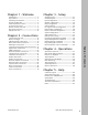
Chapter 1 - Welcome Introduction ………………………………………………… 5 Key Features………………………………………………… 5 Unpacking the GFR-700 ……………………………… 5 Placing the GFR-700 …………………………………… 6 About the Remote Control ………………………… 6 Front Panel Overview ………………………………… 7 Remote Control Overview …………………………… 8 Rear Panel Overview ……………………………………10 Display Overview …………………………………………12 Chapter 2 - Connections Setup Overview ……………………………………………31 Setup Navigation …………………………………………32 Input Configuration ………………………………………33 Speaker Configuration ……………………
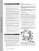
Important Safety Instructions • • • • • • • Important Safety Instructions • • • • • • • • Read all the safety and operating instructions before connecting or using this unit. Retain this notice and the owner’s manual for future reference. All warnings on the unit and in its operating instructions should be adhered to. All operating and use instructions should be followed. Do not use this unit near water.
Chapter 1 - Welcome Introduction Introducing Adcom’s new take on the A/V Receiver: the no-nonsense GFR-700. Who hasn’t grown weary of manufacturers claiming every product on offer as redefining some elusive “standards” or idealizing the ever popular catch-all, “state of the art?” Well, so have we. So instead of assaulting you with yet another slew of marketing buzzwords and hyperbolic claims, we’ll just proudly introduce to you Adcom’s latest no-nonsense product: The GFR-700 A/V Receiver.
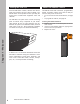
Placing the GFR-700 Place the GFR-700 on a stable, vibration-free surface away from moisture and out of direct sunlight. Your Adcom dealer will be pleased to show you many different types of audio/video equipment racks and cabinets. Chapter 1 - Welcome The GFR-700’s rear panel is the central connecting point for almost every component in your audio/ video system. Be sure to leave sufficient room behind the rear panel to accommodate cables, antenna leads, power cords, etc.
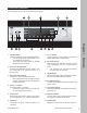
Front Panel Overview The following is an overview of the GFR-700 front panel. Standby button Powers the GFR-700 on and off (Standby mode). • The rear panel power switch must be on for this button to function. • The Power LED glows amber in Standby mode and red in On mode. 2 Room Two On/Off button Activates the GFR-700’s Zone 2 outputs, usually connected to an amplifier/receiver in a second room. 3 Room Two Setup button Displays the Zone 2 configuration menu.
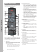
Remote Control Overview 2 Source Selector buttons • Vid 1~4 - Selects the Video 1, Video 2, Video 3, or Video 4 input, including the video, audio, and configuration settings associated with that input. Also sets the remote control to the command set associated with that input (see page 43). • CD - Selects the CD input, including all configuration settings associated with that input. Also sets the remote control to the CD command set (see page 44).
10 Mem button In Tuner mode, stores the selected station as a preset. 11 Bass button Programmable button. 12 Treble button Programmable button. 13 Sleep button Sets the sleep timer to power the GFR-700 off after a specified length of time (30~180 minutes). 14 Backlight button Turns the remote control backlight on. • The backlight times out after ~8 seconds. 15 Mute button Mutes the audio for the selected input. 17 Setup button Displays the GFR-700 Setup menu on the front panel and on-screen displays.
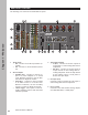
Rear Panel Overview The following is an overview of the GFR-700 rear panel.
6 7 8 Composite/S-video inputs/outputs • Video 1~4 inputs (CVBS/S-video) - Connects to the Composite/S-video outputs of up to four video source components. • Video tape output (CVBS/S-video) Connects to the Composite/S-video inputs of a video recording component. Monitor outputs/HD bypass transcoder • Video out (CVBS/S-video) - Connects to the Composite/S-video inputs of a TV, monitor, or other display device.
Display Overview The following is an overview of the GFR-700 on-screen and front panel displays. VIDEO 1 COAXIAL 1 DOLBY D -40.0 dB Chapter 1 - Welcome On-Screen Display Front Panel Display 12 1 Video source Displays the selected video source. 2 Audio source Displays the selected audio source. • In Tuner mode, displays the selected tuner frequency. 3 Surround mode Displays the selected Surround mode. • To step through Surround modes, press the Mode button.
Chapter 2 - Connections Connections Overview The GFR-700 is the heart and soul of your entertainment system. All roads lead to it (from your input devices), and all roads lead from it (to your output devices). In this chapter, you will connect the GFR700 to the various components in your home theater system.
AM/FM Antenna Connections Follow these steps to connect the supplied AM/FM antennas to the GFR-700. Connecting the AM Loop Antenna 1 Assemble the antenna. • Rotate the base until it snaps into place. 2 Connect the antenna. • Locate the AM antenna inputs. • Press the lever next to one of the terminals and insert one of the antenna leads into the terminal. Release the lever to lock the lead in place. • Repeat for the other lead. 3 Position the antenna for best reception.
Basic Audio/Video Connections 2 This section provides a general connection method that is suitable for virtually any audio/video source component, including: • DVD players • Laser disc players • CableTV boxes • Satellite receivers • HDTV set-top boxes • VCRs • PVRs 3 4 Connecting Audio/Video Components 1 Choose a Video input (1~4) for your component. A typical scenario might be: • Video 1 - DVD or Laser disc player. • Video 2 - Digital set-top box (CableTV, satellite receiver, or HDTV tuner).
DVD Player Connections The GFR-700 is a movie lover’s dream. Choose from the following special options when connecting your DVD player. Component/Progressive Scan Connections To take the video quality up a notch, use your DVD player’s Component/Progressive Scan outputs. • See page 17. Digital Audio Connections For crystal-clear multi-channel digital audio, use your DVD player’s digital audio outputs. • See page 18.
Component/Progressive Scan Connections The GFR-700 features four Component video inputs for connection to DVD players, digital CableTV boxes, digital satellite receivers, HDTV receivers/tuners, and more. Component video is the best available analog connection method to an HDTV set, and if you have a Progressive Scan DVD player, the picture quality is even more impressive. Chatper 2 - Connections Component/Progressive Scan Connections 1 Choose an available Component Video input (1~4).
Digital Audio Connections The GFR-700 features six digital audio inputs—three coaxial and three optical—to receive multi-channel bitstreams from your DVD player or other digital audio source component. Chatper 2 - Connections Connecting Digital Audio Components 1 Choose an available digital audio input. 2 Connect digital audio cable(s). • Using a digital coaxial audio cable, connect the coaxial output on your source device to the corresponding coaxial input on the GFR700.
HDMI Connections Using the HDMI Jacks HDMI, or High Definition Multimedia Interface, is an advanced audio/video connection method that transfers full-bandwidth, uncompressed digital audio and video signals over a single cable.
External Decoder Connections If you’re a true audiophile, you’re probably familiar with DVD-Audio and SACD, multi-channel audio formats that require their own decoding and unique connection methods. Follow these steps to connect a DVD, DVD-A, or SACD player with up to 7.1-channel analog outputs. ��� � Chatper 2 - Connections Connecting a DVD-A/SACD Player 1 Using eight RCA cables, connect the 7.1 channel analog audio outputs from your DVD player to the corresponding Ext 7.1 inputs on the GFR-700.
CD/Tape Player Connections Follow these steps to connect a CD or tape player to the GFR-700. Connecting a CD Player 1 Using RCA cables, connect the audio outputs on your CD player to the CD inputs on the GFR-700. • If your CD player is equipped with a digital audio output (e.g. to play back a DTS CD), see Digital Audio Connections on page 18. Connecting a Tape Player 1 Using RCA cables, connect the audio outputs on your tape player to the Tape inputs on the GFR700.
TV/Monitor Connections Component Video Connections 1 Using a Component video cable, connect the Y/Pb/Pr outputs on the GFR-700 to the corresponding Y/Pb/Pr inputs on your digital display device. 2 Be sure to match the red, green, and blue connectors accordingly.
Speaker Placement TV Placing your Speakers To enjoy the full effect of your home theater system, it is recommended that you connect a complete set of 7.1-channel surround sound speakers, including: • Front Speakers (LF/RF) • Center Speaker (C) 7 • Surround Speakers (LS/RS) • Surround Back Speakers (LB/RB) • Subwoofer (S) .1 If that’s not possible, the next best thing is a 5.1channel setup, including: • Front Speakers (LF/RF) 5 • Center Speaker (C) • Surround Speakers (LS/RS) • Subwoofer (S) .
Speaker Connections Follow these steps to connect your front (LF/RF), center (C), and surround (LS/RS) speakers. For subwoofer or surround back connections, see page 25.
External Amplifier Connections The GFR-700’s built-in 5 x 125 watts per channel amplifier has more than enough power for most home applications. Nevertheless, 7.1 preamp outputs are provided so you can hook the GFR-700 up to an even bigger rig (the GFA-7707 comes to mind), if desired. More importantly, these preamp outputs can also be used in tandem with the GFR-700’s built-in amplifier to connect a subwoofer (S) and surround back (RB/ LB) speakers.
Video Recorder Connections It’s not always about playback. Sometimes you want to record, and these days that means DVD recorders, HDD recorders, and PVRs (such as TiVo®), in addition to the old standby, the VCR. Once you’ve connected a dual playback/record device to the Video 3 or Video 4 inputs (see page 15), follow these steps to connect the GFR-700 back out to the device for record capability.
Tape Out/Aux Connections The GFR-700 includes two additional sets of RCA outputs for connection to a tape recorder and/or audio system. Follow these steps to connect your audio output device to the GFR-700. Connecting a Tape Recorder 1 Connect the tape recorder. • Using RCA cables, connect the Tape outputs on the GFR-700 to the audio inputs on your tape recorder. 2 Monitor the tape recording. • Press the Tape button on the remote control or front panel to monitor the tape output.
Room 2 Connections Connecting the 12V DC Trigger If your external device is equipped with a 12V DC trigger, you can have the device power on automatically when you select Room 2 from the GFR-700. 1 Connect the 12V DC trigger. • Using a cable with two mono mini-plugs, connect the 12V DC trigger jack from the GFR-700 to the 12V DC trigger jack on your external component. • Now when you press the Room 2 button, the sound system in Room 2 will power on automatically.
Control Connections Sensors, triggers, and PCs, oh my. If you’ve gotten this far, you’re really fine-tuning your home theater. This section is all about control: • Remote IR sensors - These allow you to control your GFR-700 even if it is behind closed doors or otherwise concealed from view. • Triggers - These allow you to automatically power on connected devices, such as motorized movie screens and connected amplifiers, when the GFR-700 is powered on or a particular input is selected.
Power Connections When all connections are complete, you’re ready to check the voltage switch, plug in the power cable, and power on the GFR-700. Checking the Voltage Switch 1 To prevent damage to your equipment, make sure the rear panel voltage switch is set correctly for your geographic region. • Select 120V for U.S. and Canada. • Select 230V for EU and Australia operation. • For other regions, check with your local authorities.
Chapter 3 - Setup Setup Overview The following is an overview of the GFR-700 Setup menu, including: • • • • • • • • • Setup navigation .................................. Input configuration ............................... Speaker configuration ............................ Delay configuration ............................... Channel balance ................................... ProLogic II/Neo:6 configuration ................. Room 2 configuration ............................. System configuration ..................
Setup Navigation Chapter 3 - Setup Use the following remote control buttons to navigate the Setup menu. • Main - Press the Main button to select the GFR700. You must first select the GRF-700 before you can access the Setup menu. • Setup - Press the Setup button to display and exit the Setup menu. • Arrows - Press the / buttons to move the selection arrow up or down the list of menu items. Press the / buttons to step through all available options for the selected menu item.
Input Configuration What options are available when you select an input source? The following is an overview of the configuration settings available for each input. To 1 2 3 access the Input Configuration menu: Press the Main button on the remote control. Press the Setup button. Use the / buttons to select INPUT CONFIG, then press the Select button. 4 Use the / buttons to choose from the following menu items: SOURCE Selects the input source you are configuring.
Speaker Configuration What speaker types and sizes are you using? The following is an overview of the Speaker Configuration menu. To 1 2 3 access the Speaker Configuration menu: Press the Main button on the remote control. Press the Setup button. Use the / buttons to select SPEAKER CONFIG, then press the Select button. 4 Use the / buttons to choose from the following menu items: FRONT Selects the relative size of your front speakers.
Delay Configuration How far is each speaker from your primary listening area? The GFR-700 uses this information to calculate differences in distance and adds milliseconds of delay if necessary to ensure that all audio signals reach your ears simultaneously from all speakers. The following is an overview of the Delay Configuration menu. To 1 2 3 access the Delay Configuration menu: Press the Main button on the remote control. Press the Setup button.
Channel Balance How can you achieve optimal balance in volume levels from all speakers? The GFR-700 supplies individual sliders and a “pink noise” test tone to aid you in balancing your speaker levels. For best results, it is recommended that you use a Sound Pressure Level (SPL) meter to precisely measure the volume levels from each speaker. However, your ear aided by experimentation is ultimately the best judge. The following is an overview of the Channel Balance menu.
Pro Logic IIx/Neo:6 Configuration The GFR-700 makes the most of your incoming stereo signals. With the built-in Dolby Pro Logic IIx and DTS Neo:6 decoders, not only can you slice, dice, and expertly distribute a stereo signal to seven or more speakers, you can even fine-tune the imaging and depth of the sound field specifically for music sources. To access the Pro Logic IIx/Neo:6 configuration menu: 1 Press the Main button on the remote control. 2 Press the Setup button.
Room 2 Basic Configuration What input source do you want to play in Room 2? Once that is specified, you have the option of fine tuning audio levels depending on the requirements of your Room 2 audio system. To 1 2 3 access the Room 2 Configuration menu: Press the Main button on the remote control. Press the Setup button. Use the / buttons to select ROOM 2 CONFIG, then press the Select button.
Room 2 Advanced Configuration The Room 2 Advanced Configuration menu contains powerful tools to customize and optimize the output of the GFR-700 to your secondary audio system. To 1 2 3 access the Room 2 Advanced Config menu: Press the Main button on the remote control. Press the Setup button. Use the / buttons to select ROOM 2 CONFIG, then press the Select button. 4 Use the / buttons to select ADVANCED SETTINGS, then press the Select button.
System Configuration The System Configuration menu provides initial power, on-screen display time outs, and system tools to put the finishing touches on your system setup. One critical tool is the “Setup Lock,” which allows you to lock down all the settings you’ve made to the GFR-700 to prevent accidental changes or tampering with the unit. To 1 2 3 access the System Configuration menu: Press the Main button on the remote control. Press the Setup button.
Analog Input Level The GFR-700 allows you to adjust the voltage reference levels independently for each of the unit’s seven analog audio inputs. Check the technical specifications of your source components to determine the optimum reference level setting. To 1 2 3 access the Analog Input Level menu: Press the Main button on the remote control. Press the Setup button. Use the / buttons to select ANALOG INPUT LEVEL, then press the Select button.
Remote Control Setup The GFR-700 is a learning remote control that is capable of storing and executing commands for all remote controls in your home theater system. In this way, you can eliminate the confusion of using multiple remotes. This section is divided into two main parts: Using Preprogrammed Commands The first section is an overview of the preprogrammed commands for each source: • Main commands ................................... 39 • Video 1~3 commands .............................
Using Preprogrammed Commands The following commands are preprogrammed for the Main and Video 1-3 inputs: Main Commands Function Selects GFR-700 codes Selects VIDEO 1 codes Selects VIDEO 2 codes Selects VIDEO 3 codes Selects VIDEO 4 codes (GDV-850) Selects CD codes (GCD-750) Selects GFR-700 Tuner codes Selects GFR-700 Room 2 codes Toggles Power On/Standby Toggles External 7.
Using Preprogrammed Commands The following commands are preprogrammed for the Video 4 and CD inputs: Video 4 (GDV-850) Commands Chapter 3 - Setup Button main vid 1 vid 2 vid 3 vid 4 CD tuner Rm. 2 power ext 7.1 tape mute setup volume volume play menu / / select pause stop mode th-eq ch-trim test 1 2 3 4 5 6 7 8 9 +10 tune + tune FM/AM/HD mem Pre/Tune St/Mon seek bass treble bypass d.
Using Preprogrammed Commands The following commands are preprogrammed for the Tuner and Room 2 inputs: Tuner Commands Function Selects GFR-700 codes Selects VIDEO 1 codes Selects VIDEO 2 codes Selects VIDEO 3 codes Selects VIDEO 4 codes (GDV-850) Selects CD codes (GCD-750) Selects GFR-700 Tuner codes Selects GFR-700 Room 2 codes Toggles Power On/Standby Programmable Toggles Tape Monitor On/Off Toggles Audio Mute On/Off GFR-700 OSD Setup Menu Master Volume UP Master Volume DN Programmable GFR-700 OSD Setup M
Programming Remote Commands Once you’re familiar with the preprogrammed commands, you may wish to program specific buttons on the GFR-700 remote to control your source components. To do this, you will need: • Your source component remote control, which will teach the new command. • The GFR-700 remote control, which will learn the new command. Chapter 3 - Setup Programming a Command 1 Place your source remote “head-to-head” with the GFR-700 remote.
Deleting Remote Commands Deleting a Command 1 On the GFR-700 remote, press the applicable Source and Select buttons simultaneously. • The orange status LED and the Source button glow and remain lit. 2 Press the button whose function you wish to clear. • The orange status LED begins flashing. 3 Press the Backlight button. • The green status LED blinks twice and then goes back to steady orange to indicate that the command has been deleted.
Programming Macro Buttons If you find yourself repeatedly pressing the same sequence of buttons while using your GFR-700, then consider taking advantage of the built-in Macro feature. Macros allow you to execute a series of commands (up to ten button presses) at the touch of a single button.
Discrete Remote Control Commands The GFR-700 can be controlled via its serial RS-232 port. The serial port can be connected to a media control center, PC, or ‘dumb terminal’ via a straight-through standard 9-pin serial port cable (MALE on one end and FEMALE on the other end). When using a PC, a terminal emulator program (e.g. HyperTerminal), can be used to control the GFR-700.
Chapter 3 - Setup Discrete Remote Control Commands 50 Function Description Data ASCII Surround Right Channel Trim - 0x44 D Function Description Data ASCII Select Source: CD 0x70 p Surround Back Left Channel Trim + 0x45 E Surround Back Left Channel Trim - 0x46 F Select Source: TUNER (AM) 0x6F o Select Source: TUNER (FM) 0x72 r Surround Back Right Channel Trim + 0x47 G TUNER Scan + 0x61 a Surround Back Right Channel Trim - 0x48 H TUNER Scan - 0x62 b Center Channel Trim +
Chapter 4 - Operations Operations Overview Now that you’ve connected and configured your GFR-700, it’s time for the fun part—enjoying the full power and performance of your Adcom system. This chapter covers: • • • • • • • • Basic Audio/Video Playback ..................... Ext. 7.1 Playback .................................. Tape Playback ..................................... Selecting Surround Modes ....................... Basic Recording .................................... Tuner Operations ...............
Basic Audio/Video Playback Follow these steps to play an audio/video source component connected to the Video 1, Video 2, Video 3, Video 4, or CD inputs. Chapter 4 - Operations Playing an AV Source Component 1 Before you begin: • Power on the GFR-700. • Power on your Source component. • Power on your TV or display device (If applicable). 2 Select your input source. • Press the desired Source selector button (Video 1, Video 2, Video 3, Video 4, or CD) on the GFR-700. 3 Play your Source component.
Selecting Surround Modes If source components are the main course in your home entertainment center, then Surround modes provide the special sauce. Surround modes process incoming audio signals and distribute them to your speakers—with each mode configured to bring out the unique flavor of your source material and send just the right mix to suit your personal taste and specific speaker configuration. • To set the default Surround mode for each input, see page 33.
Other Surround Modes 7.1 m2 Uses an Adcom-proprietary digital processing technology to expand incoming stereo signals to 7.1-channel surround sound. Use if: • Your source component is connected to the analog or digital audio inputs. • Your source audio is in 2-channel analog or digital PCM format. • You have seven speakers plus a subwoofer. Chapter 4 - Operations STEREO Passes an incoming or downmixed stereo signal to the front speakers.
Basic Recording Follow these steps make a recording using the playback and recording components connected to the GFR-700. You will first need to identify your Source and Target components. • Source - This can be the AM/FM tuner or any connected audio/video device (e.g, a cable box, DVD player, VCR, etc.). • Target - This can be any connected recording device (e.g., a VCR, DVD recorder, PVR, tape recorder, etc.). www.adcom.com 4 5 Cue your Source device.
Tuner Operations Follow these steps to use the GFR-700’s built-in AM/ FM tuner. Before you begin, make sure the AM/FM antennas are properly connected; see page 14. Selecting Tuner Mode To select Tuner mode: • Press the Tuner button on the remote control. or • Press the FM/AM button on the front panel. Selecting the Tuner Band To switch between the AM/FM bands: • Press the FM/AM/HD button on the remote control. or • Press the FM/AM button on the front panel.
System Operations The GFR-700 includes additional features that enhance the user experience, including a built-in sleep timer and front panel display dimmer. Using the Sleep Timer If you enjoy falling asleep while watching TV or listening to music, you can use the sleep timer to automatically power off the GFR-700 after a set period of time. Using the Front Panel Display Dimmer The front panel display has three brightness levels to suit any need.
Room 2 Operations The Room 2 feature makes the GFR-700 a true multitasking device. For example, you can watch a movie in one room and play a CD in another at the touch of a button. To use the Room 2 feature, you must have: • An amplifier or receiver connected to the Zone 2 Outputs; see page 28. • A Room 2 input source specified in the Setup menu; see page 38. Chapter 4 - Operations Activating the Room 2 Output To activate the Room 2 output: 1 Power on the GFR-700. 2 Select the Room 2 output.
Chapter 5 - Help Customer Support Use the Troubleshooting chart on page 60 to resolve common situations that don’t require professional attention. If the information provided does not resolve your problem, please contact your Adcom dealer or contact the Adcom customer service department as follows: Adcom, LLC 8541 E. Anderson Dr., Suite 101 Scottsdale, Arizona 85255 • Telephone: (480) 607-2277 • Fax: (480) 348-9876 • Email: service@adcom.com • Web: www.adcom.
Troubleshooting The table below shows possible causes and solutions to common GFR-700 issues. If you do not see the answers you need here, please contact your Adcom dealer or customer service department; see page 59.
Technical Specifications PREAMPLIFIER ANALOG SECTION PREAMPLIFIER DIGITAL SECTION Frequency Response • Digital Input ............10Hz to 22kHz +0/-0.2dB THD+N (@ Rated Input & Output) • Digital Input ................. 0.009% (A-weighted) S/N Ratio (ref. 2.0Vrms A-weighted) • Digital Input .................................... 99dB Bass Management (Front/Center/Surround/Sub) • High-Pass Slope .............Crossover Frequency • (Small Spkr Setting) .... 12dB/octave (2nd order) (Adj.
Index A I S Analog Input Level 41 Audio Cables 13 Input Configuration 33 On-Screen Display 12, 22 Setup Navigation 32 Overview 31 Sleep Timer 57 Speaker Configuration 34 Connections 24 Placement 23 Surround Modes Dolby 53 DTS 53 Selecting 53 Sync 9, 33, 52 System Configuration 40 System Operations 57 P T Placement 6 Playback Basic Audio/Video 52 External 7.
Adcom shall not be liable for any errors contained herein or for any damages arising out of or related to this document or the information contained herein, even if Adcom has been advised of the possibility of such damages. This document is intended for informational and instructional purposes only. Adcom reserves the right to make changes in the specifications and other information contained in this document without prior notification.
8541 East Anderson Drive, Suite 101 Scottsdale, Arizona 85255 Voice: 480.607.2277 Fax: 480.348.9876 www.adcom.com GFR-700_manual_v2.