GRouter4 Single Port 709.1 /852 LON/IP Router User Guide 4.
Copyright © 2007 by Adept Systems, Inc. All Rights Reserved. Printed in USA. Version 4.05, June 2007. This document, the associated software, and the associated online documentation are the property of Adept Systems, Inc. and are loaned to the user under the terms of the End User License Agreement. No title to or ownership of the software described in this document or any of its parts is transferred to customers.
Table of Contents Overview ...................................................................................................7 1. 1.1. Introduction ...........................................................................................7 1.2. Configuration Parameters .....................................................................9 1.3. 1.3.1. 1.3.2. Modes of Operation ............................................................................10 Manual Mode...................................
2.3.2. 2.3.3. 2.4. IP Setup Page ........................................................................................40 2.5. WiFi Setup Page....................................................................................42 2.6. 2.6.1. 2.6.2. 709 Setup Page......................................................................................44 Node Parameters ............................................................................44 Forwarding Tables..........................................
List Of Figures Figure 1.1: Network Layers...................................................................................................8 Figure 1.2: Network Connector Types and Associated Layers ...........................................8 Figure 1.3: CN to IP Router/Gateway Architecture ............................................................9 Figure 1.4: GRouter 3 Architecture......................................................................................9 Figure 1.
Figure 2.19: Diagnostics Page ............................................................................................52 Figure 2.20: Dynamic DNS Configuration Page...............................................................54 Figure 2.21: Twin Mode Setup Page...................................................................................55 Figure 2.22: Twin Mode Status Page ..................................................................................58 Figure 2.23: Contacts Page ............
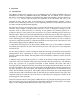
1. Overview 1.1. Introduction The GRouter (GR4) router supports two open standard protocols, namely ANSI/EIA 709.1 and ANSI/EIA 852. Both the ANSI/EIA 709.1 and ANSI/EIA 852 are defined by the Consumer Electronics Association Technology & Standards R7.1 HCS1 Subcommittee. For more details see http://ce.org/. For the sake of brevity the remainder of the document will refer to the standards as 709.1 and 852. 709.1 is also known by its trademarked name, LonTalk®. A 709.
Fig.1.1: Network Layers A network connector is a device that joins different parts of a network. Connectors have a specific name that is dependent on the layer at which the connector operates. For example a router operates at the network layer and a gateway at the application layer. Because higher layers of the protocol do not have access to some of the information stripped away by lower layers, network connectors operating at different layers have different capabilities.
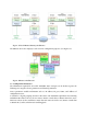
Fig.1.3: CN to IP Router/Gateway Architecture The GRouter device also employs a web server for configuration purposes. (See Figure 2.4) Fig.1.4: GRouter 3 Architecture 1.2. Configuration Parameters The information required for successful ANSI/EIA 709.1 transport can be broken up into the following two categories: device parameters and channel parameters. Device parameters include information such as: IP address, IP port, Name, and Address of configuration server.
A channel, then, is defined as a group of routers that all send information to each other. The lines of communication are open in both directions and to all members—a complete mesh of connections. Typically, channels are managed through the use of a configuration server (called Normal mode see below). The configuration server informs all members in the channel about the channel information, which includes the adding and removing of channel members.
support to ANSI/EIA 709.1 networks. This allows multi-building or multi-site connection of automation networks. Internet Fig.1.5: Multi-site building automation network with internet connectivity 1.4.2. IP backbones for LON traffic aggregation Furthermore, since the IP networks can support much higher traffic capacity, GRouter devices can also be used to aggregate 709.1 traffic from several LON channels over one IP channel.
Remote Monitoring Configuration Internet Node ... Node 78 kbps LON Ethernet Optional WiFi to Ethernet Bridge Ad Hoc 802.11b WiFi Channel LON/WiFi Routers 78 kbps LON Node ... 78 kbps LON Node Node ... Node Fig.1.7: Example WiFi Ad Hoc Network 1.4.3. Roaming Connections Finally, LON to IP gateways may be connected to specialized IP applications instead of to other gateways.
Multicast is not a concern when all the 852 devices share the same subnet. The following figures illustrate the differences between multicast and unicast. E D Destination Unit-Cast Packet Destination IP Network Internet Unit-Cast Packet Unit-Cast Packet Unit-Cast Packet Destination Source B A C ANSI 852 709.1/IP Gateway/Router Node ... Node Destination ANSI 852 709.1/IP Gateway/Router Node ... Node Node ... Node Fig.1.
1.6. 852 to 852 Bridging Router Mode In order to better support large installations with dozens of IP to LON routers a GRouter device can be configured in 852 to 852 bridging router mode. In this mode one GRouter device can bridge two logical 852 channels. When acting as an 852 bridge the router is a member of two logical 852 channels sharing one ethernet interface. The router bridges traffic between the two channels. On the LON side the bridge looks like a LON router.
1.7. Redundant Twin Mode The Twin Redundant Mode enables two GRouter devices to operate as a redundant pair for high availability applications without generating duplicate traffic. This enhanced capability increases reliability and eliminates some single mode failure sources. A simple diagram showing a redundant connection between two channels is shown below. IP Ethernet Channel Ethernet 709 with 852 Ethernet Router IP/LON 709 with LON 709 with LON FTT-10 FTT-10 Router IP/LON 709 with 852 709.
Ethernet 852 Ethernet Router IP/LON 709 Redundant Twin Routers FTT-10 Router IP/LON 709 852 FTT-10 A-1 B-1 FTT-10 Channel Ring Ethernet 852 Ethernet Router IP/LON 709 Redundant Twin Routers FTT-10 A-2 Router IP/LON 709 852 FTT-10 B-2 FTT-10 Channel Ring Network Management Tool & 852 Configuration Server 852 Interface Ethernet 852 Channel A Fully Switched Ethernet Ethernet Switch Ethernet 852 Channel B Fully Switched Ethernet Switch Fig.1.
1.7.1. Definitions For the purpose of clarifying the descriptions the following definitions are used: Failure: A failure is detected whenever a heart beat times out without receiving a monitoring packet from both interfaces. Only the active node sends monitoring packets. The inactive node passively listens for the monitoring packets. The inactive twin always forwards monitoring packets.
comm_failure is set to 1 when there is either a monitoring failure or comm_failure is not set to 0 until all failures and faults have cleared. a diagnostic detects a fault. reserved2 is set based on the system state. See the following table.
is an 8 bit number. The bit definitions are given in Table 1. It is the same information reported in the Status SNVT reserved field. Status totalArbs is the total number of active state arbitrations since the last time the statistics were cleared. totalFailuresIP is the total number monitoring packet failures detected by this device of the IP interface since the statistics were cleared.
1.8. System Requirements and Connections 1.8.1. System Requirements To configure the GRouter device, you will need a web browser such as FireFox, Mozilla, Safari, or Internet Explorer. The GRouter device will communicate with any of the following: • Adept Systems Inc. GRouter4, GRouter3, or GadgetGatewayIa (GG1a) 852 router • Echelon i.
1.8.2. Button, Indicators, and Connectors for GRouter 8 1 9 2 3 4 12 7 Index 1 Ethernet 10/100 Base-T Port. RJ-45 Cat-5. 8 9 10 11 12 13 14 15 15 11 6 7 14 10 5 2 3 4 5 6 13 Description Power LED lights when unit powered. Service LED flashes when a service message sent. TX LED flashes to indicate send traffic on the LON Port. RX LED flashes to indicate receive traffic on the LON Port. LON (709.1) Port. May be either FTT-10 or RS-485 transceiver. Check particular configuration of router.
block unscrew the terminal screws on the block and insert the ends of the appropriate wires into each opening. Tighten the terminal screws. Pins A and B are the 709.1 LON channel port pins. For FTT-10 transceivers, use the A and B pins. The pins are polarity insensitive. For RS-485 transceivers use the A and B pins appropriately and insert the RS-485 ground lead into the terminal block pin with the input pins labeled (ground) symbol next to the pin labeled A. There are two power (logic ground) and 5VDC.
internal terminator is installed, a jumper on header JP1 is used to configure the type of termination. In order to do this the case must be opened. Disconnect the power and network before opening the case. Use caution and appropriate electrostatic safety precautions whenever working with the case removed. If the center pin of JP1 is jumpered to the pin labeled Free, then the terminator is set for free topology mode.
2. Web Configuration The Web-based GRouter device interface allows the user to access and change configuration data on the GRouter device by using any http Web browser attached to the network. This allows users to make changes to the GRouter device remotely. This chapter familiarizes the user with the various pages of the Web-based Interface and describes the steps necessary to changing configuration data. 2.1.
Cat5 CrossOver Cable Fig.2.2: Ethernet with direct connect crossover cable 2.1.2. WiFi (802.11b) For WiFi equipped GRouter devices, an 802.11b WiFi access point or ad hoc connection must be setup between the web browser host computer and the GRouter device. First configure the host computer to add an IP interface on subnet 10.0.2.0/255. Then setup the WiFi configuration.
Ethernet Ad Hoc Bridge Fig.2.4: WiFi setup with ad hoc bridge and Ethernet connection to host computer Fig.2.5: WiFi setup with ad hoc WiFi card on PC Access Point Fig.2.
2.1.3. Establishing Connection Once the IP connection (WiFi or Ethernet) is setup, power up the GRouter device. It takes about 60 seconds for the GRouter device to boot up. Boot-up has completed when the yellow User LEDs start flashing. To verify that the IP connection has been made send an IP ping to the GRouter device default IP host address (10.0.2.40). In Linux, Windows 2k+, or Mac OS X a ping can be sent from the command line as follows: ping 10.0.2.40 Then type enter or return.
• Reboot GRouter device and reestablish communications using new settings • If communications with new settings cannot be established because of lost or incorrect settings then revert GRouter device to factory defaults and start over. 2.1.4. Restoring Factory Defaults The web Tool allows customization of the IP address, net mask, http port, user name, and password. Should any of these settings be forgotten or setup incorrectly, communication with the GRouter device may not be possible.
2.1.5. WiFi Setup in Windows XP • Go to the network connections control panel. Right click wireless connection and select properties. • Select the general tab. Set the IP address to one that is in the same subnet as the GRouter’s default IP of 10.0.2.40 with a subnet mask of 255.255.255.0. For example you could use 10.0.2.41. • Go to network properties and select the connection tab. Select manual connect to an available wireless network not automatically connect.
2.2. Status Page The status page is the home page for the web Tool. The buttons shown on the left will vary depending on what optional services have been enabled in the router. The Router Status Page displays basic information about the status of the Router. Changes to the data cannot be made through this page; it is for information purposes only. Following is a brief description of each item shown on the page Fig.2.8: Status Page NAME: The given name of the router.
IP MAC ADDRESS: The IP MAC or hardware address assigned to the router's IP port. IP ADDRESS: The IP address assigned to the router. NODE ID (709.1): The 709.1-side (LON) unique Node ID number assigned to the router. If 852 bridge mode is enabled this is the near side of the router. NODE ID (IP): The IP-side unique Node ID number assigned to the router. If 852 bridge mode is enabled this is the far side of the router.
2.3. Router Setup Page The Router Basic Setup Page is used to set up basic configuration properties of the router. Following is a brief description of each item listed on the page, as well as instructions on how to set or change items. 2.3.1. Normal Mode Router Setup When not in bridging mode the Normal mode router setup page looks like the following. Fig.2.9: Router Setup Page MODE: This displays the current operating mode of the router.
• Manual Mode: Use manual mode when precise control over the Channel List is desired. In manual mode the user is responsible for the configuration of the Channel List. • Normal Mode: Use normal mode when the router is being configured by a remote configuration server. When in Normal mode, ensure that the Config Server Address is correct (see Config Server Address below). Router Name: This field allows the user to set or change the name of the router.
The GRouter device’s LAN address must also be static and the 852 port must be mapped by the NAT router. NAT Router Support: These radio buttons allow the user to set or enable or disable NAT router support. When enabled the node substitutes the NAT Router WAN Address as the source address in appropriate packet headers so that other 852 nodes can respond through the NAT Router. This enables 852 devices that are on other LANs on the WAN side of the NAT router to correctly respond to the local GRouter device.
added to a channel or their routing data is changed. This may be helpful for low bandwidth 852 channels. Select the new value and click the Submit Changes button. Serial Transaction Interval: This field sets the time interval between successive configuration transactions when Serial Transaction Mode is enabled. The default is 1000 ms. This enables the user throttle the rate at which configuration updates are sent out on the channel and thereby manage traffic.
when moving the router to a different 852 channel or configuration and a known starting configuration is desirable.. Reboot: This button performs a soft reboot of the main processor on the router. This is needed any time the ports are changed or the 852 Bridge mode is changed. When rebooting the following page will be displayed. Fig.2.10: Reboot Page Once rebooting has completed reenter http://10.0.2.40 or whatever the IP address of the router is to go back to the Status page. 2.3.2.
2.3.3. Bridging Router Setup When 852 to 852 bridging router mode is enabled the GG router has two IP side 852 interfaces. One is labeled the Side A and the other the Side B. Both interfaces share the same IP host address but each interface has a unique IP port and a unique configuration server (when in Normal mode). Each side can be in either Normal or Manual mode independently. In addition, Serial Transaction Mode can be independently enabled or disabled on each side.
Fig.2.
Side A Data IP Port: This field appears when the router is in 852 bridge mode. It allows the user to set or change the Side A unicast IP port of the router. To change the port, type in the new port number (0-65535), and click the Submit Changes button. Side A ConfigServer IP Address: This field appears only when the router is operating in 852 Bridge mode and Side A is in Normal Mode. This is the unicast IP host address of the configuration server for the Side A 852 channel.
2.4. IP Setup Page The IP Setup Page displays status additional information about the Gateway's IP setup not included in the Router Setup page. Following is a brief description of each item listed on the page, as well as instructions on how to set or change items. In normal mode the page looks like the following. Fig.2.12: IP Setup Page MAC Address: The physical address of the Ethernet interface in HEX. This is a read only field. IP Address: The IP address currently assigned to the Gateway.
port 80 may be in use by another device. The device must be restarted before changes to the webserver port will be activated. To change the value, type in the new value and click the Submit Changes button and then click the Reboot button. A typical alternate web server port is 8080. To access the web server on any port other than 80, use the following format in the web browser: http://IP Address:Port for example http://10.0.2.
2.5. WiFi Setup Page For GRouter devices equipped with WiFi IP interfaces the WiFi setup button will appear and will display the WiFi setup page. MODE: This displays the WiFi channel access mode of the router. To change the WiFi mode, select the the desired mode in the popup menu and then click the Submit Changes button. The mode will not change until after a reboot. The Four possible modes are Any type, Infrastructure, Ad hoc (join or create), and Ad hoc (join only).
• Ad hoc (join or create): Use this mode for creating an ad hoc network if one does not exist or joining one that already exists with the chosen SSID • Ad hoc (join only): Use this mode for joining an existing ad hoc network SSID: To change the SSID of the WiFi channel, type the new value into the field provided and click the Submit Changes button. Channel: To change the WiFi channel number select it from the popup menu. To search for an available channel, select Search.
2.6. 709 Setup Page The 709 Setup Page is used to set up the 709.1 protocol specific properties of the router. This information includes the subnet address, node address, domain address, node ID and node state numbers for both sides of the router and the twin mode monitoring application (when enabled) as well as the subnet and group forwarding tables. Following is a brief description of each item listed on the page, as well as instructions on how to set or change items.
Subnet: When a node is unconfigured the subnet may be zero. Valid configured subnet numbers are from 1 to 255. Enter the subnet number then click Submit Changes. Node: When a node is unconfigured the node number may be zero. Valid configured node numbers are from 1 to 127. Enter the node number then click Submit Changes. Domain Number: The number of valid domains is a function of the Domain Length. Zero is a valid domain number but is reserved for network management.
Set Group Table: This button sets all the group bits by assigning each a value of one and stores the new values in memory. Fig.2.14: Subnet Forwarding Table Fig.2.
2.7. Channel List Page In Normal mode the Channel Membership List is controlled by the configuration server. Whereas in Manual mode the Channel Membership List must be configured manually. This page allows the user to add and delete the devices from the 852 channel when in Manual mode. Following is a brief description of each item listed on the page, as well as instructions on how to set or change items. The behavior of the page is different for Normal and Manual mode. 2.7.1.
Channel Date Time: This is the 852 DateTime when the Channel Membership List was last changed. This is a read only field for debugging purposes. In Normal mode, this value is governed by the configuration server. Channel Time Out: This is the 852 Channel Time Out. This is a read only field for debugging purposes. In Normal mode, this value is governed by the configuration server.. Channel Address Mode: Is either Unicast or Multicast. Multicast is only supported in manual mode.
Fig.2.17: Channel List Page in Manual Mode Channel Date Time: This is the 852 DateTime when the Channel Membership List was last changed. This is a read only field for debugging purposes. In Manual mode, this value is updated whenever a device is added to the channel list. Channel Time Out: This is the 852 Channel Time Out in milliseconds. Enter the desired value and click Submit Changes. Channel Address Mode: Is either Unicast or Multicast. Multicast is only supported in manual mode.
ending in ".0 " are reserved. Some addresses ending in ".1" are used for multicast host broadcasts and should also be avoided. Examples of valid multicast addresses include: 225.0.0.2, 225.0.0.3, 225.1.2.3. You may need to check with your network administrator to see what multicast addresses are available for your use. Enter the desired value and click Submit Changes. Packet Escrow: These radio buttons enable or disable Packet escrow mode.
Fig.2.18: Device Detail Page Device Name: The name of the device. IP Address: The current IP address of the device. IP Port: The current IP Port number on which the device is communicating. Multicast Address: The address that the device uses if it is set to multicast addressing. Channel Name: The name of the channel to which the device belongs. IP Support: The protocols supported by this device. These include UDP, TCP, and Multicast. 709.1 Router Type: The type of router of the device.
2.9. Diagnostics Page The Diagnostics Page provides statistics about the performance of the router. This page is helpful in debugging configuration as it can show that packets are being forwarded across the router.. Following is a brief description of each item listed on the page, as well as instructions on how to set or change items. Fig.2.19: Diagnostics Page Seconds Since Cleared: This is the number of seconds since the statistics were cleared. This is a read only field for debugging purposes.
Number of Channel Members: This is the number of devices in the 852 channel. In Bridging Mode this only provides the number of devices in the NearSide channel. This is a read only field for debugging purposes. Forward Rate (PPS): This is the average number of packets per second forwarded by the router since the statistics were cleared. This is a read only field for debugging purposes. 709.
2.10. DDNS Setup Page The DDNS Setup Page allows the configuration of DDNS capability. This page only appears when in manual mode. Following is a brief description of each item listed on the page. Fig.2.20: Dynamic DNS Configuration Page DDNS Name: The is the domain name for the associated NAT router that includes DDNS support. The DDNS name is hosted by dyndns.com. DDNS IP Address: This is the current WAN address of the NAT router.
2.11. Twin Setup Page This page configures the twin mode redundant router feature. Twin mode is an optional enhancement and is not activated in a standard router. If your device does not support redundant twin mode contact Adept to find out how redundant twin mode might be activated. This page does not appear if NAT support is enabled. Following is a brief description of each item listed on the page Fig.2.
Time + Cushion, both monitoring packets are not detected by a router then a monitoring failure has been deemed to have occurred. The routers then go to an active diagnostic mode. The cushion should always be less than the HeartBeat Time but greater than the expected latency due to propagation delays. The default is 200 ms. AutoSync Time: This sets the time period in milliseconds between automatic synchronization attempts from the twin to the inactive twin. The default is 5000 ms.
between propagations. If the update time is non zero, every update time ms a status SNVT is scheduled for propagation. It is propagated even if the status has not been updated. If the update time is zero then no propagation is scheduled on a timed interval. For a more detailed description of the Status SNVT see Section 2.5.5. Status SNVT Send on Update: This option schedules the status SNVT for propagation whenever the SNVT is updated or the status changes. This is event driven and not time driven.
2.12. Twin Mode Status Page The Twin Mode Status Page displays operational state and statistics information about the Redundant Twin Mode operation. Twin mode is an optional enhancement and is not activated in a standard router. If your device does not support Redundant Twin Mode contact Adept to find out how it might be activated. Following is a brief description of each item listed on the page. Fig.2.
Seconds Since Clear: This field indicates the number of seconds since the statistics were last cleared. Arb Count: This field indicates this device’s arbitration count. Twin Arb Count: This field indicates the twin’s arbitration count. Total Arbitrations: This field indicates the total number of active state arbitrations. Forward Rate: This field indicates the rate in packets per second of packets forwarded by the router in either direction.
2.13. Contacts Page The Contacts Page contains contact information and links for Adept Systems, Inc. Fig.2.
3. Network Integration and Management 3.1. Manual Mode Example Configuring in Manual Mode This section contains step-by-step instructions on configuring two GRouter devices to tunnel 709.1 packets over IP between each other. This will create an IP backbone for a 709.1 network. • Using the web configuration pages, set up IP addresses, subnet masks, and IP gateway addresses for the two routers. Connect the routers to the same IP network.
Fig.3.1: Configuration Server Screen • Verify that the GRouter device is configured correctly by checking the Channel List Page on the router. If configured correctly, the router will have an entry in its Channel List for each router shown in the configuration server’s channel list. • The routers will now communicate with each other over IP and will tunnel packets between networks once they have been commissioned using LonMaker or another compatible network management tool. 3.3.
“Commission Members” option. After a few seconds, both the LonMaker PC and the GRouter devices will turn green. • You will now be able to install and commission the GRouter devices as 709.1 routers in the LonMaker network diagram. 3.4. Commissioning GRouter Device With LonMaker There are two ways that a network management tool such as LonMaker can communicate with and commission a GRouter device.
Fig.3.2: Initial LonMaker Drawing Fig.3.
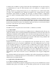
Fig.3.4: Service Pin Dialog Fig.3.5: Fully Commissioned Router 3.5. NAT Router Example This section contains step-by-step instructions on how to set up a GadgetGateway router for operation on the LAN side of a NAT router. The NAT support mode enables a GRouter device to operate on the LAN side of a NAT (Network Address Translation) router. The setup is shown in the following figure.
WAN WAN Internet DSL/Cable Modem LAN to WAN Router Static or Dynamic Public IP Address NAT Port Map DDNS Client 10/100 Ethernet LAN 10/100 Ethernet LAN LON/IP Router Private Static IP Address NAT Port Mapped LON Network Node LON Network Node Network Managment Node Node Fig.3.6: NAT LAN to WAN Architecture • Setup the IP parameters for the GRouter as per the Manual Mode or Normal Mode instructions above. • Configure the NAT router to port map the 852 port.
DDNS domain name for the NAT-DDNS router, you must go to dyndns.org and register for one. • Verify DDNS is working by doing a manual look up the IP address using either the web or serial interface. The router’s DDNS IP address should show up in the DDNS IP Address field. • Continue configuring the GRouter device in manual mode to add other 852 devices to its channel etc. 3.7.
• On router A’s Twin Mode Setup Page, enable Twin Mode by selecting the associated ON radio button. The routers will now act as a redundant pair. • Go to the Twin Status Page to observe operational state and failure statistics. • The monitoring application on each router is now ready to be commissioned. Repeat the following steps for each router. • Drag a new device shape onto the LonMaker drawing. The device should be attached to the channel on the LON side of the GRouter device.
Fig.3.8: LonMaker New Device Channel Dialog Fig.3.
Fig.3.10: New Virtual Functional Device Dialog Fig.3.
Fig.3.12: Functional Block On Drawing 3.8. Configuring with the Coactive Router-LL 3.8.1. Manual Mode This section contains step-by-step instructions on configuring a Coactive Router-LL and a GRouter device in manual mode to tunnel 709.1 packets between each other over IP. • Using the web configuration pages for the GRouter and the serial menu for the Router-LL, set up IP addresses, subnet masks, and IP gateway addresses for the two routers. Connect the routers to the same IP network.
3.8.2. Normal Mode With Router-LL Configuration Server • Using the web configuration pages, set up IP address(es), subnet mask(s), and IP gateway address(es) for the router(s). Connect the router(s) to the same IP network. Using a PC attached to the network, verify that the routers can be pinged. Consult with the network administrator to procure the IP address, subnet mask, and gateway address, if not already known. • Set the router(s) to normal mode.
4. Firmware Upgrade Instructions The GRouter device's firmware can be upgraded using ftp over the IP interface. This feature allows GRouter device users to take advantage of enhancements and features that may become available in the future. First obtain a copy of the new firmware ROM file named *.bin, such as newrom.bin In order to perform an update, the FTP server application must be running on the GRouter device.