
Manual

3-34 IETG FlowHawk Manual
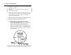
depth and velocity. In addition, measure the horizontal and vertical
pipe dimensions carefully. Even slightly inaccurate pipe
dimensions can significantly skew and misrepresent flow data.
Caution: Handle all sensors and cables with extreme
care. The sensors and cables contain delicate mechanisms
and electronics. Keep sharp objects away from sensor
cables, and avoid stepping or placing heavy objects on the
cable during installation. Avoid contacting the metal
connector at the end of the Surface Combo Sensor cable
with the Teflon-coated crystals on the sensor.
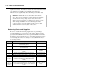
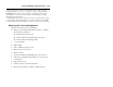
Gathering Parts and Supplies
Be sure to obtain the following supplies before performing a
special installation to prevent any costly delays. When ordering,
specify the FlowHawk flow monitor special installation hardware.
In addition, please indicate the type of mounting hardware desired
for mounting the monitor: mounting bracket (wall/rim mount) or
hook (rung mount).
Quantity Description Part Number
1 FlowHawk flow monitor (includes internal 12-
volt IS battery pack)
8000-FHK-60C
1 Monitor mounting bracket (for mounting monitor
to manhole wall)
I40–0009
3 Monitor mounting bracket bolt, hex, SS, M8 X
30mm
508058
3 Monitor mounting bracket washer, flat, SS 517-8001254-00
3 Monitor mounting bracket washer, split lock, SS 517-8001274-00
1 as
needed
Hook, SS, 2-piece w/ hardware (for hanging
monitor on manhole rung. Alternative to I40-
0009)
8000-0021
Up to 2
(1 per
monitoring
point)
Peak Combo Sensor – upward ultrasonic depth
sensor, pressure depth sensor, & peak velocity
sensor w/ M3 x 6mm stainless steel, flathead
screws
8K-CS4-xx-35/1H
(10.6m or 30.5m
cable)
1