AR-B1851 User’s Guide AR-B1851 Pentium M inside,EPIC form factor ,On Board VGA,LVDS with DDR SO-DIMM, built in Two LAN,CF Type-II Edition: 1.
AR-B1851 User’s Guide @Copyright 2005 All Rights Reserved. Manual first edition Nov 22, 2005 The information in this document is subject to change without prior notice in order to improve reliability, design and function and does not represent a commitment on the part of the manufacturer.
AR-B1851 User’s Guide Contents Contents ................................................................ 3 Introduction ............................................................. 5 1.1 Specifications: ....................................................................... 5 1.2 What You Have ..................................................................... 7 Installation .............................................................. 8 2.1 AR-B1851’s Layout ......................................
AR-B1851 User’s Guide 3.9 AUDIO Connector(AUDIO1) ............................................... 18 3.10 DDR SODIMM Socket (J1) ................................................. 19 3.11 8-BIT GPIO Connector(GPIO1) .......................................... 19 3.12 Parallel port(PRN1) ............................................................. 20 3.13 LVDS Connector(LVDS1) ................................................... 20 3.14 Speak Connector(SPK1)...................................................
AR-B1851 User’s Guide 1 Introduction 1.1 Specifications: CPU : Supports Intel Pentium M, Celeron M CPU. Chipset : GMCH 852GM and ICH4 82801DB RAM memory : DDR SDRAM SO-DIMM Socket support to 1GB/266MHz. Display Controller: Intel 852GM Supports non-interlaced CRT monitors Supports LVDS Encoders. Ultra DMA 133 IDE Interface : One PCI Enhance IDE channel. TM TM CompactFlash interface : Supports CompactFlash Compact Flash Disk or IBM Micro Drive.
AR-B1851 User’s Guide Power Consumption : 12V / 5V Operating Temperature : -10° ~ 60° C ( CPU needs Cooler) Dimension: 146mm(W) X 101.
AR-B1851 User’s Guide 1.
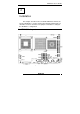
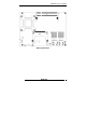
AR-B1851 User’s Guide 2 Installation This chapter describes how to install the AR-B1851. At first, the layout of AR-B1851 is shown, and the unpacking information that you should be careful is described. The jumpers and switches setting for the AR-B1851’s configuration 2.
AR-B1851 User’s Guide Bottom Placement AR-B1851 9
AR-B1851 User’s Guide 2.
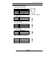
AR-B1851 User’s Guide • CN8 : Power ON Pin Header Pin 1 2 3 DESCRIPTION GND PS_ON 5VSB 2.3 CMOS Reset • JP1 : CMOS pin header JP1 1-2 2-3 DESCRIPTION Normal Operation Clear CMOS 2.
AR-B1851 User’s Guide • JP4 : Select COM4 is RS232 or RS422/485 JP4 1-2 2-3 Description RS232 RS422/485 • JP6 : Select LCD Voltage JP6 1-2 2-3 Description +3.
AR-B1851 User’s Guide 3 Connection This chapter describes how to connect peripherals, switches and indicators to the AR-B1851 board. 3.1 Ultra ATA33/66/100 IDE Disk Drive Connector(IDE1) You can attach two IDE( Integrated Device Electronics) hard disk drives to the AR-B1851 IDE controller. IDE 1 : Secondary IDE Connector (44 Pins) PIN NO.
AR-B1851 User’s Guide 3.2 Serial Ports(COM1~4) The AR-B1851 offers two high speeds NS16C550 compatible UARTs with Read/Receive 16 byte FIFO serial ports.
AR-B1851 User’s Guide 3.3 Keyboard / Mouse Connector(MS_KB1) A PS/2 type connector(MS_KB1)is for easy connection to a keyboard and PS/2 mouse. The board comes with a Y split PS/2 cable for keyboard and mouse connection. • KB/MS1 : Keyboard Mouse PS2 Port PIN 1 3 5 7 DESCRIPTION KB_DAT GND +5V X PIN 2 4 6 8 DESCRIPTION MS_DAT X KB_CLK MS_CLK 3.4 USB Port Connector(USB1~4) The AR-B1851 provides four USB port, four pin header, two connectors .
AR-B1851 User’s Guide 3.5 Fan Connector (FAN1) The AR-B1851 provides one connectors for CPU cooling fan they can be controlled by Super I/O Chip. • FAN1: Fan Connector for CPU PIN NO. 1 2 3 DESCRIPTION GND +12V PWM Signal 3.6 LAN RJ45 Connector (LAN1/2) AR-B1851 is equipped with built-in 10/100Mbps(Option) or 1000MbpsEthernet Controller. You can connect it to your LAN through RJ45 LAN connector. The pin assignments are as following: • LAN1/2 : LAN RJ45 Connector PIN NO. DESCRIPTION 1 TX+ 2 TX3. RX+ 4.
AR-B1851 User’s Guide 3.7 Compact Flash Storage Card Socket(CF1) The AR-B1851 configures Compact Flash Storage Card in IDE Mode. This type II Socket is compatible with IBM Micro Drive. •CF1 : Compact Flash Storage Card Socket pin assignment PIN NO. 1 2 3 4 5 6 7 8 9 10 11 12 13 14 15 16 17 18 19 20 21 22 23 24 25 DESCRIPTION GROUND D3 D4 D5 D6 D7 CS1# N/C GROUND N/C N/C N/C VCC N/C N/C N/C N/C A2 A1 A0 D0 D1 D2 N/C CARD DETECT2 PIN NO.
AR-B1851 User’s Guide 3.8 VGA Connector(VGA1) The AR-B1851 has a built-in 15-pin VGA connector accepting the CRT monitor • VGA1 : 15-pin D-Sub Connector PIN 1 3 5 7 9 11 13 15 DESCRIPTION L_RED L_BLUE GND GND +5V MONOPU HSYNC 5VDDCCL PIN 2 4 6 8 10 12 14 DESCRIPTION L_GREEN MON2PU GND GND GND 5VDDCDA VSYNC NOTE: When system boots up without the MONITOR attached during the POST, the VBIOS will disable the MONITOR output.
AR-B1851 User’s Guide 3.10 DDR SODIMM Socket (J1) There are two 200-pin DDR SDRAM DIMM slots to accept 2.5V non_buffered DDR SDRAM. The max Memory size is 2GB. • J1 : DDR SODIMM Socket 3.11 8-BIT GPIO Connector(GPIO1) • GPIO1: 8 BIT GPIO Connector PIN 1 3 5 7 9 DESCRIPTION GP10 GP12 GP14 GP16 GND PIN 2 4 6 8 10 DESCRIPTION GP11 GP13 GP15 GP17 VCC 3.14 Speak Connector(SPK1) • SPK1 : Speak out Connector(through Amplifier) PIN NO.
AR-B1851 User’s Guide 3.12 Parallel port(PRN1) This port is usually connected to a printer. The AR-B1851 includes an on-board parallel port. • PRN1: Parallel Port Connector PIN 1 2 3 4 5 6 7 8 9 10 11 12 13 DESCRIPTION STBPD0 PD1 PD2 PD3 PD4 PD5 PD6 PD7 ACKBUSY PE SLCT PIN 14 15 16 17 18 19 20 21 22 23 24 25 26 DESCRIPTION AFDERRINITSLINGND GND GND GND GND GND GND GND X 3.
AR-B1851 User’s Guide 4 Award BIOS Setup 4.1 Introduction This chapter discusses the Setup program built into the BIOS. The Setup program allows users to configure the system. This configuration is then stored in battery-backed CMOS RAM so that it retains the Setup information while the power is off. 4.2 Starting Setup The BIOS is immediately active when you turn on the computer. While the BIOS is in control, the Setup program can be activated in one of two ways: 1.
AR-B1851 User’s Guide In general, you can use the arrow keys to highlight items, press to select, use the PageUp and PageDown keys to change entries, press for help and press to quit. The following table provides more details about how to navigate in the Setup program using the keyboard.
AR-B1851 User’s Guide 4.4 Main Menu The items in Standard CMOS Setup Menu are divided into 10 categories. Each category includes no, one or more than one setup items. Use the arrow keys to highlight the item and then use the or keys to select the value you want in each item.
AR-B1851 User’s Guide Secondary Slave Base Memory menu (described in Table 3) None 360K, 5.25 in 1.2M, 5.25 in 1.720K, 3.5 in 1.44K, 3.5 in 2.88K, 3.
AR-B1851 User’s Guide Cylinder 0 Head 0 Precomp 0 Landing Zone 0 Sector 0 Figure 2 IDE Primary Master sub menu Use the legend keys to navigate through this menu and exit to the main menu. Use Table 2 to configure the hard disk. Item IDE HDD Auto-detection Options Press Enter IDE Primary Master None Auto Manual Capacity Auto Display your disk drive size Access Mode CHS LBA Large Auto Description Press Enter to auto-detect the HDD on this channel.
AR-B1851 User’s Guide 4.5 Advanced BIOS Features This section allows you to configure your system for basic operation. Figure 3 Advanced menu APIC Mode This item allows use Advanced Programmable Interrupt Controller feature.The Choice: Enabled, Disabled. Quick Power On Self Test This category speeds up Power On Self Test (POST) after you power up the computer. If it is set to Enable, BIOS will shorten or skip some check items during POST.
AR-B1851 User’s Guide PS/2 Mouse Function Disabled-prevents any installed PS/2 mouse from functioning but frees up IRQ12.Enabled-allows the operating system to determine whether to enable or disable the mouse. Choice: Enabled, Disabled. Init Display First This item allows you to choose which Display to be first detected. The Choice: PCI Slot, On Board / AGP. Intel VGA Share Memory This item allows you to Choose the Frame Buffer size for Display. The Choice: 1MB, 4MB, 8MB, 16MB, 32MB.
AR-B1851 User’s Guide 4.6 PnP/PCI Configuration Setup Figure 4 PnP/PCI menu Resource controlled by The Award Plug and Play BIOS has the capacity to automatically configure all of the boot and Plug and Play compatible devices. However, this capability means absolutely nothing unless you are using a Plug and Play operating system such as Windows®95. If you set this field to “manual” choose specific resources by going into each of the sub menu that follows this field (a sub menu is preceded by a “ ”).
AR-B1851 User’s Guide 4.7 Peripheral Figure 5 Peripheral menu Onboard Serial Port 1/Port 2 Select an address and corresponding interrupt for the first and second serial ports. The choice: 3F8/IRQ4, 2E8/IRQ3, 3E8/IRQ4, 2F8/IRQ3, Disabled, Auto UART Mode Select Select the Function Mode for UART. The choice: IrDA, ASKIR, Normal Onboard Serial Port 3/Port 4 Select an address and corresponding interrupt for the first and second serial ports.
AR-B1851 User’s Guide Onboard Parallel Port Select 3BC/IRQ7 to enable On Board Parallel Port as first Parallel Interface. The choice: Disable, 378/IRQ7, 278/IRQ5, 3BC/IRQ7. USB Controller Select Enabled if your system contains a Universal Serial Bus (USB) controller and you have USB peripherals. The Choice: Enabled, Disabled. USB 2.0 Controller This Entry is for disable / enable EHCI controller only. The Bios itself may / may not have high speed USB support.
AR-B1851 User’s Guide 4.8 PC Health Figure 5 H/W Monitor menu Shutdown Temperature This item allows the system to reset when temperature reach the trigger level.
AR-B1851 User’s Guide 4.9 Boot Figure 6 Boot menu First/Second/Third/Other Boot Device The BIOS attempts to load the operating system from the devices in the sequence selected in these items. The Choice: Floppy……….[ ] LS120……….[ ] Hard Disk ….[ ] CDROM……….[ ] ZIP100 ……….[ ] USB-FDD ..…...[ ] USB-ZIP ..…...[ ] USB-CDROM ..[▪] On Board LAN…[ ] Disabled…..
AR-B1851 User’s Guide 4.10 Exit Selecting Save & Exit Setup Load Optimized Defaults Exit Without Saving Load Fail-Save Default Figure 8 Exit menu Save & Exit Setup Pressing on this item asks for confirmation: Save to CMOS and EXIT (Y/N)? Y Pressing “Y” stores the selections made in the menus in CMOS – a special section of memory that stays on after you turn your system off. The next time you boot your computer, the BIOS configures your system according to the Setup selections stored in CMOS.
AR-B1851 User’s Guide Use this menu to load the BIOS default values that are factory settings for optimal performance system operations. While Award has designed the custom BIOS to maximize performance, the factory has the right to change these defaults to meet their needs. When you press on this item you get a confirmation dialog box with a message similar to: Load Optimized Defaults (Y/N) ? N Pressing ‘Y’ loads the default values that are factory settings for optimal performance system operations.
AR-B1851 User’s Guide Appendix A. Watchdog Timer The WDT(Watch Dog Timer)is used to generate a variety of output signals after a user programmable cont. The WDT is suitable for use in the prevention of system lock-up, such as when software becomes trapped in a deadlock. Under these sort of circumstances, the timer will count to zero and the selected outputs will be driven. Under normal circumstance, the user will restart the WDT at regular intervals before the timer counts to zero.
AR-B1851 User’s Guide Appendix B: Digital I/O One characteristic of digital circuit is its fast response to high or low signal. This kind of response is highly needed for harsh and critical industrial operating environment. Digital Input and Output, generally, are control signals. You can use these signals to control external devices that needs On/Off circuit or TTL devices. You can read or write data to the selected address to enable the function of digital IO.
AR-B1851 User’s Guide GPI Example O 2E 87 O 2E 87 O 2E 2A O 2F FC O 2E 07 O 2F 07 O 2E 30 O 2F 01 O 2E F0 O 2F FF O 2E F1 I 2F Q Description ;Extended Functions Enable Register ;Extended Functions Enable Register ;select CR2A ;(Define the PINs as GPIO or Game Port1)”FC”Pin121~128 set as GPIO ;EFIR=EFER(Extended Functions Index Register)point to Logical Device Number Reg.
AR-B1851 User’s Guide Appendix C: I/O Address Map I/O ADDRESS MAP I/O ADDRESS MAP DESCRIPTION 00000000-0000000F DMA Controller 00000000-00000CF7 PCI Bus 00000010-0000001F Mainboard Resource 00000020-00000021 Programable Interrupt Controller 00000022-0000003F Mainboard Resource 00000040-00000043 System Timer 00000044-0000005F Mainboard Resource 00000060-00000060 Standard 101/102 keyboard Controller 00000061-00000061 System Speaker 00000062-00000063 Mainboard Resource 00000064-00000064 Standard 101/102 keybo
AR-B1851 User’s Guide 000003B0-000003BB 000003C0-000003DF 000003E8-000003EF 000003F6-000003F6 000003F8-000003FF 00000400-000004BF 000004D0-000004D1 00000500-0000051F 00000778-0000077B 00000A78-00000A7B 00000B78-00000B7B 00000BBC-00000BBF 00000D00-0000FFFF 00000E78-00000E7B 00000F78-00000F7B 00000FBC-00000FBF 0000D000-0000D03F 0000D100-0000D13F 0000E000-0000E0FF 0000E800-0000E81F 0000E900-0000E907 0000EB00-0000EB1F 0000EC00-0000EC3F 0000ED00-0000ED1F 0000F000-0000F00F Graphics Controller Graphics Controller
AR-B1851 User’s Guide 000FC000-000FFFFF 00100000-1DFEFFFF 1DFF0000-1DFFFFFF 1E000000-FEBFFFFF D8000000-DFFFFFFF E0000000-E7FFFFFF E8000000-E801FFFF E8020000-E803FFFF E8050000-E8050FFF E8051000-E8051FFF E8100000-E817FFFF E8180000-E81FFFFF E8200000-E82003FF E8201000-E82011FF E8202000-E82020FF FEBFFC00-FEBFFFFF FEC00000-FECFFFFF FEE00000-FEEFFFFF FFB00000-FFB7FFFF FFB00000-FFBFFFFF FFF80000-FFFFFFFF System Mainboard System Mainboard System Mainboard PCI Bus Graphics Controller Graphics Controller 100M Network
AR-B1851 User’s Guide IRQ Mapping Chart IRQ0(ISA) System Timer IRQ1(ISA) Keyboard IRQ3(ISA) COM2 IRQ4(ISA) COM1 IRQ8(ISA) System CMOS/RTC IRQ9I(ISA) ACPI-Compliant IRQ10(ISA) COM4 IRQ11(ISA) COM3 IRQ12(ISA) Mouse IRQ13(ISA) Math Coprocessor IRQ14(ISA) Primary IDE IRQ15(ISA) IRQ9(PCI) IRQ16(PCI) IRQ16(PCI) IRQ17(PCI) IRQ18(PCI) IRQ19(PCI) IRQ20(PCI) IRQ21(PCI) IRQ23(PCI) Secondary IDE SMBus USB Universal Graphics AC’97 USB Universal USB Universal Network #2 Network USB2 Enhanced DMA Channel Assignments CH