ADT-1090-INT 7/25/00 3:12 PM Page 1
ADT-1090-INT 7/25/00 3:12 PM Page 2
Table of Contents * System Reference ................................................. 2 Operating Your System ......................................... 3 ....................................................................................... 3 ARMING Arming The System Prior To Leaving ..................................... 3 Arming The System Without Leaving ..................................... 3 System Will Not Arm (Ready Light Off) .................................. 4 DISARMING .........................
;“““““““““‘““““““““’ Zone Identification Card Space is provided for recording the areas of protection which are assigned to each zone. Depending upon the installation, this card pulls out from the left or right side of the control station. : lndlvldual Zone Status i If lighted, zone is not secure. i Chedc doors, windows, etc. ! H not lighted, zone is secure. i___~bll~~~~~_~~~~_~_bypassed. , 1 ! i ; i , ! I , Ready status /flight& the system is ready to be armed.
Operating Your System ARMING Before the control can be armed, all of the intrusion zones must be secure as indicated by the green READY indicator. If the READY indicator is off, one or more zones are faulted. The indicator(s) corresponding to the faulted zone(s) will light. Use the pull out zone I.D. card on the control station to determine the areas of protection which are assigned to each of the six (6) zones, thencheckthe appropriate doors and windows to see that they are closed. 1.
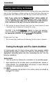
;I Turning Off the lnterlor Zones and Entrance Delay Control station key 4 may be used to turn the interior zones off prior to arming. This will allow the system to alarm instantly if the entrance door is opened, while armed. 1. Press the 4 key and hold for three seconds. 2. When interior defined zones are turned off, the corresponding Zone indicators will flash. The flashing will stop 30 seconds after the system is armed. 3. Arm the system by entering your User Code.
DISARMING Your system is programmed with one or more entrance delay zones which allow time to enter the premises without causing an alarm. Each delay door may be programmed with a different entry time. Be sure to check with your installer. Note: If your system has the “Interior Follower” feature enabled, all interior designated zones automatically become delay zones whenever you first enter through a delay zone.
ALARM CONDITIONS Whenever an alarm occurs, the ALARM indicator will light, the audible alarm will sound (if applicable), and the control wilI communicate with the central station (if this option was purchased). NOTE: If upon returning to the premises it 1s discovered that an alarm has occurred, DO NOT ENTER THE PREMISES. Leave immediately and go to the nearest phone and contact the appropriate authorities. 0 To reset the alarm: 1. Enter your User Code to reset the alarm. 2.
THE EMERGENCY KEYPAD PANIC ALARMS Your system may have been purchased with up to three emergency keypad panic alarms. These may be used to activate an alarm in the event of a Fire, Hold-up, or other emergency condition, as programmed by your installer. Each alarm is activated by pressing the appropriate emergency panic key (located below the numeric keys). Each alarm may be audible or silent. It may also be programmed to report the condition to a central monitoring station.
SPECIAL FEATURES The CHIME mode allows audible monitoring of zones while the system is disarmed. When the CHIME mode is active, the control station sounder will beep whenever a perimeter burglar defined zone (door, window, etc.) indicator is opened. For example, the CHIME feature will cause the control station to beep two times whenever the front door has been opened. Many businesses use this type of signal to announce that a customer has entered.
The bypass key (#) is used to bypass selected zones in your system. A bypassed zone will NOT be capable of activating an alarm as it is temporarily removed from your system. Bypassing (also referred to as shunting) is most commonly used to allow free movement of an area (zone or group of zones) while arming the rest of the system or to temporarily remove a zone or zones that require service allowing partial use of the system until repaired.
Your system may utilize a conventional key switch for arming and disarming the system. Arming and disarming with a key switch is performed as follows: cl Arming 1. Verify that the BEADY light is on. 2. Insert your key into the key switch and turn. Hold for one second and release. 3. The red ARMED light will blink during the exit delay cycle and then light steady when the system arms. 0 Disarming 1. Insert your key into the key switch and turn. Hold for one second and release. 2.
Programming Certain features of your system are programmable through the control station. The programming mode is entered by pressing key 9 and holding for three seconds, then entering the Master User Code. Other programming functions may be possible that are not detailed in this section. Consult your security representative for a list of the user programmable features of your system.
Determine your desired new User Code or Master User Code sequence. If you make an error while programming, press the “ * ” key five times and start over from step 1. WARNING: Pressing the “ # ” or l4 * ” key while programmlng a code may result In Improper code operation, therefore you MUST return to step 1 when an error Is made. 0 To Change A User Code 1. The system must be disarmed. 2. Press key 9 and hold for three seconds. The control station will beep three times. 3. Enter the Master User Code.
An optional feature of your system allows you to assign a certain number of valid uses to User Code 6. After the code has been used the programmed amount of times, it automatically becomes disabled. This code may be assigned to a maintenance person, a maid, or anyone who you would like to be able to arm and disarm the system for a selected number of times without having to give out your regular code. After the uses have expired, the code will cease to function.
Notes
The TEST mode commands the control station to beep continuously and light the corresponding zone indicator, each time a zone is violated. The zone indicator of each tested zone will remain lighted while each succeeding zone is tested. Testing can be performed only while the system is disarmed. Testing the system should be performed in both ELECTRICAL ROWER AC ON and STANDBY BATTERY modes. Your neighbors’ understanding and cooperation is very important.
FIRE DETECTION Your system may or may not include fire detection, depending upon what options were purchased, and the local codes and regulations for your area. Fire alarm systems are active 24 hours a day and cannot be turned off. A!! fire systems require regular testing and maintenance. Common household dust build-up in smoke detectors can cause them to false alarm or fail in a time of need. Consult your security representative for a scheduled maintenance program. 1.
Emergency Evacuation Plan Preparation and education are of prime importance in the prevention of fire. An emergency evacuation plan should be established BEFORE an emergency situation arises. Your system may or may not contain fire detection and notification equipment. Be sure to have your installer explain and that you fully understand exactly what your system consists of. Use the following steps in establishing an emergency evacuation plan: 1.
The purpose of heat and smoke detectors is to detect a fire in its earliest stages and sound an alarm, giving occupants more time to exit the premises before smoke reaches a dangerous level. Cl KNOW FIRE HAZARDS No detection device can protect life in all situations; therefore, safeguards should be taken to avoid such potentially dangerous situations as smoking in bed, leaving children home alone, and cleaning with flammable liquids such as gasoline.
0 Smoke Detector Location Smoke detectors should be installed in accordance with theNational FireProtection Association (NFPA) Standard 74. The following is from NFPA 74: Smoke detectors shall be installed outside of each separate sleeping area in the immediate vicinity of the bedrooms and on each additional story of the family living unit including basement and excluding crawl spaces and unfinishedattics (see illustration below). For family living units with one or more split levels (i.e.
Smoke Detector Placement 4 inches @lm) -_I NOTE: Allmae~~mmennts are to the closest edge of the dote&or A Smoke Detector should be located between the sleeping area and the rest of the family living unit. A Smoke Detector should be located on each story. l Indicates required smoke detector @ Indicates smoke detector is optional if door is not provided between living and recreational rooms.
Glossary Alarm Memory: A history of the alarm that last occurred. Arm: To turn the intrusion detection system on. Bypass: To temporarily remove a zone from operation. To Shunt a zone. Control Panel: The main system electronics housed in a metal enclosure. Control Station: The remote station used to enter instructions to the control panel such as to arm, disarm amd bypass. Also called a keypad.
ADT-1090-INT 7/25/00 3:13 PM Page 12
ADT-1090-INT 7/25/00 3:13 PM Page 12
Notes 20
FCC COMPLIANCE This equipment ganerates and uses radio frequency energy and lf nU installed and used properly, that !a. In strict accordance with the rtwnufacturer’s instructions, may catae interference to radio and teledslon raceptlon. lt has been type tested and found to corrpiy with the llmks for a Class B corrputlng devtce In acwtdance with the specHications of Subpart J or pan 15 of FCC rules. which are designed to pmvlde reasonable pmtectlon against such Interference in a residential Installatfon.
Sentrol, Inc resen~es MOOSE the rtght to change specifmtmns wthout notice tJ1991 Sentrol.