ADT Security Services, Inc. One Town Center Road Boca Raton, FL 33431 Phone: (561) 988-3600 FAX: (561) 988-3675 Unimode9600 Addressable Fire Alarm Control Panel Programming, Installation, Maintenance and Operating Instruction Manual IMPORTANT! The Signaling Line Circuit Wiring Manual Document #51520 must be referenced in addition to this manual when installing or servicing the Fire Alarm Control Panel.
Fire Alarm System Limitations While a fire alarm system may lower insurance rates, it is not a substitute for fire insurance! An automatic fire alarm system–typically made up of smoke detectors, heat detectors, manual pull stations, audible warning devices, and a fire alarm control with remote notification capability–can provide early warning of a developing fire. Such a system, however, does not assure protection against property damage or loss of life resulting from a fire.
Installation Precautions Adherence to the following will aid in problem-free installation with long-term reliability: WARNING - Several different sources of power can be connected to the fire alarm control panel. Disconnect all sources of power before servicing. Control unit and associated equipment may be damaged by removing and/or inserting cards, modules, or interconnecting cables while the unit is energized.
Notes 4 Unimode 9600 PN 51336:C 11/06/01
Table of Contents SECTION 1: Product Description ........................................................................................................................12 1.1: Inventory .....................................................................................................................................................12 1.2: Features and Options ...................................................................................................................................12 1.
Table of Contents 3.6.1.2.1 Add Module .........................................................................................................................53 3.6.1.2.2 Delete Module ......................................................................................................................54 3.6.1.2.3 Edit Module Screen for Monitor Module .............................................................................54 3.6.1.2.4 Edit Module Screen for Control Modules ..........................
Table of Contents 3.7.5: System ...............................................................................................................................................101 3.7.6: Zone Setup ........................................................................................................................................103 SECTION 4: Operating Instructions ....................................................................................................................105 4.
Table of Contents 5.4.1: NFPA Battery Requirements .............................................................................................................130 5.4.2: Selecting and Locating Batteries.......................................................................................................130 APPENDIX A: Software Zones ............................................................................................................................131 A.1: Correlations ............................
It is imperative that the installer understand the requirements of the Authority Having Jurisdiction (AHJ) and be familiar with the standards set forth by the following regulatory agencies: • • • Underwriters Laboratories Standards NFPA 72 National Fire Alarm Code CAN/ULC - S527M Standard for Control Units for Fire Alarm Systems Before proceeding, the installer should be familiar with the following documents.
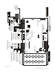
Unimode 9600 PN 51336:C 11/06/01 9600lay3.cdr CAUTION! 2 1 + + - B A A B B A A B + + - - + + - - J17 DISABLE GND FLT JP2 TB4 4XTMF OPT BD 120 VAC, 60 HZ, 3.2 amps HOT NEUT EARTH TB1 LCD DISPLAY A Fail Safe Trouble NC NO C relay switches to the NO position during trouble conditions and under loss of all power.
Peripheral Devices and Their Documents: ADT-AFM-16AT & ADT-AFM-32A Doc. # A15048 ADT-ACS Series Doc. # 51353 ADT-ACM-8R Doc. # 51356 ACS (EIA-485) Annunciators ADT-AFM-16A Doc. # A15207 Ack/Step TERM (EIA-485) Annunciators Silence Drill Hold 2 sec. ADT-LDM-32 Doc. # 51351 Reset ADT-LCD-80F Doc. # 51589 Unimode 9600 Doc. # 51336 1 SLC Loop 9600peri.cdr ADT-UDACT Doc. # 50934 Addressable Devices and SLC Wiring Doc. # 51309 Battery Connector ADT-CHG-120 Charger Doc.
3URGXFW 'HVFULSWLRQ ,QYHQWRU\ Product Description SECTION 1 The ADT Unimode 9600 is a compact, cost effective, intelligent addressable FACP (Fire Alarm Control Panel) with an extensive list of powerful features. The combination of newer series devices and legacy 300 Series devices, along with the Unimode 9600 FACP, offer the latest in fire protection technology.
Features and Options Product Description • Annunciators: • ✓ ADT-AFM-LED Zone Annunciator Series ✓ ADT-LDM Graphic Annunciator Series ✓ ADT-LCD-80F Liquid Crystal Display point annunciator ✓ ADT-ACM-8R Relay Module Silence inhibit timer option per NAC • Autosilence timer option per NAC • Continuous, March Time, Temporal or California code for main circuit board NACs with two-stage capability • Selectable strobe synchronization per NAC • Remote Acknowledge, Alarm Silence, Reset and Drill via addr
Product Description Specifications 1.3 Specifications AC Power - TB1 120 VAC, 60 Hz, 3.2 amps Wire size: minimum 14 AWG (2.00 mm2) with 600 V insulation Battery (Lead Acid Only) - TB2 Maximum Charging Circuit: Normal Flat Charge - 27.6 VDC @ 1.00 amp Maximum Battery Charger Capacity: 25 Amp Hour (Unimode 9600 cabinet holds maximum of two 18 Amp Hour batteries. For greater than 25 Amp Hour up to 120 Amp Hour batteries, use the ADT-CHG-120 Battery Charger and BB-55F Battery Box.
Specifications Product Description EIA-485 (ACS) - TB6 ACS annunciator connector, Terminal 1 (+) and Terminal 2 (-) EIA-485 (TERM) - TB7 Terminal Mode annunciator connector, Terminal 5 (In +), 6 (In -), 7 (Out +), 8 (Out -) EIA-232 (ACS) - TB7 PC/Printer Connector, Terminal 1 (Transmit), 2 (Receive), 3 (DTR), 4 (Ground) Auxiliary Trouble Inputs - J16 & J17 Two-pin connectors which can be used to monitor trouble conditions on auxiliary equipment.
Product Description Controls and Indicators 1.4 Controls and Indicators LCD Display The FACP uses an 80-character (4 lines X 20 characters) high viewing angle LCD display. The display includes a long life LED backlight that remains illuminated. If AC power is lost and the system is not in alarm, the LED backlight will turn off to conserve batteries.
Circuits Product Description 1.5 Circuits SLC Communication Loop Reference Manual One SLC loop is provided standard on the FACP main circuit board. A second SLC loop is available by plugging the optional SLC module into connector J3 on the main circuit board. SLC loops, configurable for NFPA Style 4, 6 or 7, provide communication to addressable detectors, monitor (initiating device) and control (output device) modules. Refer to the ADT SLC Wiring Manual for information on wiring devices.
Product Description Components Cabinet uni-600.cdr The Unimode 9600 cabinet is red with a navy blue front overlay. The backbox provides space for two batteries (up to 18 Amp Hour). Ample knockouts are provided for system wiring. Also included is a standard dress panel, which mounts to the inside of the cabinet (required on the ULC version). The dress panel must be installed to meet FM requirements. Batteries The Unimode 9600 cabinet provides space for two batteries (up to 18 Amp Hour).
Components Product Description 1.6.2 Intelligent Addressable Modules: Newer Series Reference Manual The newer series of Control Modules and Monitor Modules provide an interface between the control panel and conventional notification and initiating devices. Each module can be set to respond to an address with built-in rotary switches with the ability to select up to 159 addresses (a tab on the address switch must be broken off to use addresses 100-159).
Product Description Optional Modules 1.6.3 300 Series Intelligent Addressable Devices ADT’s 300 Series Intelligent Addressable Devices are fully compatible with the Unimode 9600 FACP. The devices must be configured for CLIP Mode operation if the control panel is installed in an existing system with 300 Series devices. The address of 300 Series devices cannot be set above 99.
Accessories Product Description 1.8 Accessories 1.8.1 PK-9600 Programming Utility The PK-9600 Programming Utility can be used to program an Unimode 9600 directly from most IBM compatible computers, including laptops and portables, equipped with a serial port. Unimode 9600 program files can also be created and stored on the PC and then downloaded to the control panel. The PK-9600 Kit includes the Windows-based Programming Utility software on CD-ROM with on-line help file.
Product Description Accessories BB-55F bb-55f.cdr The BB-55F battery box may be used to house two 25 AH batteries, two 60 AH batteries or one 100 AH battery. When the ADT-CHG-120 is mounted in the BB-55F, two 25 AH or one 60 AH battery may also be housed in the battery box. 1.8.4 ADT-CHG-120 Battery Charger Reference Manual The ADT-CHG-120 is capable of charging up to 120 AH lead-acid batteries with the Unimode 9600 FACP. The FACP battery charger must be disabled when using the ADT-CHG-120.
Getting Started Product Description ADT-LCD-80F Remote Fire Annunciator The ADT-LCD-80F annunciator is a compact 80-character backlit LCD remote fire annunciator that is capable of displaying English language text. It mimics the display on the control panel and will annunciate device type, point alarm, trouble or supervisory condition, zone assignment plus any custom alpha labels programmed into the FACP.
Installation Mounting Installation SECTION 2 The cabinet may be either semi-flush or surface mounted. The cabinet mounts using two key slots and two 0.250” (6.35 mm) diameter holes located in the backbox. The key slots are located at the top of the backbox and the two securing holes at the bottom. Carefully unpack the system and check for shipping damage. Mount the cabinet in a clean, dry, vibration-free area where extreme temperatures are not encountered.
Mounting Installation 1.75“ 5.1 cm 2.00“ 2.00“ 2.00“ 2.00“ 2.00“ 2.00“ 4.45 cm 1.75“ 1.50“ (3.81 cm) 3.79 cm 1.49“ 4.1 cm 1.62“ 15.5“ (39.37 cm) 1.62“ (4.11 cm) 3.81 cm 1.50“ 12.00“ (30.48 cm) 4.1cm 1.62“ 1.453“ (3.69 cm) 10.0“ 25.4 cm 47.0cm 18.5“ 4.45cm 1.75“ 17.35 cm 6.83“ 4.45cm 1.75“ 4.1cm 1.583“ 1.50“ 3.81 cm 4.37“ 11.1 cm 9600encl.cdr 11.1 cm 4.37“ 1.50“ (3.81 cm) 1.75“ 4.45 cm Figure 2.
Installation Mounting Depth = 4.37" (11.1 cm) Top Depth = 4.425" (11.24 cm) Door = 15.78" (40.08 cm) Backbox = 15.5" (39.37 cm) Door = 18.67" (47.43 cm) Backbox = 18.5" (47.0 cm) Left Side Right Side Bottom 18.620" (47.3 cm) Depth = 4.75" (12.07 cm) 15.625" (39.688 cm) 21.620" (54.92 cm) Battery Box = 8.5" (21.59 cm) 9600cab.cdr 18.625" (47.308 cm) Trim Ring P/N:FC-TR Battery Box = 14.34" (36.42 cm) Figure 2.
Power Installation 2.2 Power WARNING: Several different sources of power can be connected to this panel. Disconnect all sources of power before servicing. The panel and associated equipment may be damaged by removing and/or inserting cards, modules or interconnecting cables while this unit is energized. 2.2.1 AC Power and Earth Ground Connection LCD DISPLAY Primary power required for the FACP is 120 VAC, TB1 TB2 60 Hz, 3.2 amps.
Installation Relays 2.3 Relays The FACP provides two programmable Form-C relays and one fixed fail-safe Form-C trouble relay, all with contacts rated for 2.0 amps @ 30 VDC (resistive) or 0.5 amps @ 30 VAC (resistive). The Alarm and Supervisory silk-screen labels reflect the factory default programming for the two programmable relays. Note that relay connections may be power-limited or nonpower-limited, provided that 0.
UL Power-limited Wiring Requirements Installation 2.5 UL Power-limited Wiring Requirements Power-limited and nonpower-limited circuit wiring must remain separated in the cabinet. All power-limited circuit wiring must remain at least 0.25” (6.35 mm) away from any nonpower-limited circuit wiring and nonpower-limited circuit wiring must enter and exit the cabinet through different knockouts and/or conduits. A typical wiring diagram for the Unimode 9600 is shown below.
Installation Optional Modules and Devices 2.6 Optional Modules and Devices WARNING! Disconnect all sources of power (AC and DC) before installing or removing any modules or wiring. Unimode 9600 Keypad/Display Removal Removal of the keypad/display is normally not necessary.
2SWLRQDO 0RGXOHV DQG 'HYLFHV ,QVWDOODWLRQ 2.6.1 4XTMF Transmitter Module Installation The 4XTMF provides a supervised output for a local energy municipal box transmitter in addition to alarm and trouble reverse polarity. A jumper option allows the reverse polarity circuit to open with a system trouble condition if no alarm condition exists. A disable switch allows disabling of the transmitter output during testing to prevent accidental calling of the monitoring service.
,QVWDOODWLRQ 2SWLRQDO 0RGXOHV DQG 'HYLFHV The following steps must be followed when installing the 4XTMF module: 1. Remove all power (AC and DC) from the FACP before installing 4XTMF 2. Cut jumper JP6 on the main circuit board to allow the control panel to supervise the 4XTMF module 3. Carefully plug the connectors on the 4XTMF module into connectors J10 and J11 on the Unimode 9600 main circuit board, being careful not to bend any pins 4. Secure 4XTMF module to standoffs with supplied screws. 5.
2SWLRQDO 0RGXOHV DQG 'HYLFHV ,QVWDOODWLRQ 2.6.3 SLC-2 Expander Module Reference Manual The optional SLC-2 Expander Module provides a second SLC loop for the Unimode 9600 control panel. This allows connection of an additional 318 addressable devices, bringing the total to 636 addressable devices which can be connected to the FACP. Refer to the SLC Manual for information on connecting devices to the SLC. The following steps must be followed when installing the SLC-2 Expander Module: 1.
,QVWDOODWLRQ 2SWLRQDO 0RGXOHV DQG 'HYLFHV 2.6.4 Printer/PC A serial printer or a PC (personal computer) may be connected to TB7 Terminals 1 - 4 on the FACP. The printer can be used to provide a hard-copy printout of real-time events, history file and walktest data. An IBM compatible PC can be connected to provide local FACP programming capabilities using the PK-9600 programming utility. Installation of either device requires panel programming to allow the FACP to communicate with the device.
2SWLRQDO 0RGXOHV DQG 'HYLFHV ,QVWDOODWLRQ 2.6.5 Digital Communicator and Annunciators 2.6.5.1 ADT-UDACT Digital Alarm Communicator/Transmitter Reference Manual See Page 7KH $'7 8'$&7 WUDQVPLWV V\VWHP VWDWXV WR 8/ OLVWHG &HQWUDO 6WDWLRQ UHFHLYHUV YLD WKH SXEOLF VZLWFKHG WHOHSKRQH QHWZRUN ,W LV FDSDEOH RI UHSRUWLQJ XS WR VRIWZDUH ]RQHV RU XS WR DGGUHVVDEOH SRLQWV 7KH $'7 8'$&7 FDQ EH PRXQWHG UHPRWHO\ LQ D 8%6 ) RU $'7 $%6 5) HQFORVXUH RU LQ WKH SDQHO FDELQHW XVLQJ WKH 3 1 %5.
,QVWDOODWLRQ 2SWLRQDO 0RGXOHV DQG 'HYLFHV 0RGXOH ,QVWDOODWLRQ RQ %5.7 7KH IROORZLQJ PRGXOHV FDQ EH LQVWDOOHG LQVLGH WKH 8QLPRGH FDELQHW XVLQJ WKH %5.7 8QLYHUVDO %UDFNHW ✓ ADT-UDACT Digital Alarm Communicator/Transmitter - installs at standoff location (A) ✓ ADT-ACM-8R Annunciator Control Module (Relay) - installs at standoff location (A) 5HIHU WR WKH DSSURSULDWH PRGXOH PDQXDO IRU GHWDLOHG LQIRUPDWLRQ RQ PRGXOH RSHUDWLRQ DQG ZLULQJ 1.
2SWLRQDO 0RGXOHV DQG 'HYLFHV ,QVWDOODWLRQ 2.6.5.
3URJUDPPLQJ SECTION 3 3URJUDPPLQJ 'DWD (QWU\ Programming 3.1 Programming Data Entry Programming can be accomplished using the Unimode 9600 keypad or by connecting an optional standard computer keyboard. The keyboard can be connected to the PS-2 connector J7 on the control panel main circuit board. The information presented in this section refers to programming the Unimode 9600 via the onboard keypad.
8VHU 3URJUDPPLQJ 3URJUDPPLQJ 3.2 User Programming !! The Unimode 9600 is completely field programmable and requires no special software skills. While programming the Unimode 9600, the fire protection capabilities of the control panel are enabled. Site-specific programming may be accomplished in three ways: • Autoprogramming Feature - This is a convenient method for quickly bringing the FACP addressable SLC devices on-line without the necessity of programming each device individually.
3URJUDPPLQJ ,QLWLDO 3RZHU XS User Programming Levels There are two user programming levels: • User Master Program Level 1 is used for programming panel specific data relating to device types, zoning, messages, control panel functions, etc. • User Maintenance Program Level 2 is used by a qualified operator to access features such as Disable/Enable, View and Clear History, Walktest and System Time Change. 3.
3URJUDPPLQJ DQG 3DVVZRUGV 3URJUDPPLQJ To access user Programming mode, press the Enter or Mode key. The LCD will display the following: 1=READ@STATUS 2=PROGRAMMING To enter the user Programming mode, press 2.
3URJUDPPLQJ 0DVWHU 3URJUDPPLQJ /HYHO 3.6 Master Programming Level When the Master Program Level password is entered, the control panel will enter user Programming mode. In this mode, the piezo sounder remains off, the trouble relay is activated and the system Trouble LED flashes until Programming mode is exited.
0DVWHU 3URJUDPPLQJ /HYHO 3URJUDPPLQJ 3.6.1 Point Program PROGRAMMING 1=POINT PROGRAM 2=ZONE SETUP 3=LOOP SETUP Programming Screen #1 The Point Program option allows the programmer to add a new addressable device to an SLC loop, delete an existing device from a loop or change the programming for an existing device.
3URJUDPPLQJ 0DVWHU 3URJUDPPLQJ /HYHO :KHQ WKH ODVW GLJLW LV NH\HG LQ WKH IROORZLQJ VFUHHQ ZLOO EH GLVSOD\HG @@@@ADD@DETECTOR DETECTOR#@@@@@@@005 IS@ADDED 7KH SURJUDPPHU FDQ FRQWLQXH DGGLQJ GHWHFWRUV E\ SUHVVLQJ WKH (6& RU OHIW DUURZ NH\ ZKLFK ZLOO UHWXUQ WKH GLVSOD\ WR WKH $GG 'HWHFWRU 6FUHHQ DETECTOR 1=ADD 2=DELETE 3=EDIT Detector Screen 3.6.1.1.
0DVWHU 3URJUDPPLQJ /HYHO 3URJUDPPLQJ :KHQ WKH ODVW GLJLW LV NH\HG LQ LI WKH VHOHFWHG DGGUHVV KDV QRW EHHQ DGGHG WR SURJUDPPLQJ D VFUHHQ VKRZLQJ LQIRUPDWLRQ DERXW D GHYLFH ZLWK WKH KLJKHVW DGGUHVV WKDW LV LQVWDOOHG ZLOO EH GLVSOD\HG ,I QR GHWHFWRUV KDYH EHHQ LQVWDOOHG RQ WKH ORRS WKH IROORZLQJ ZLOO EH GLVSOD\HG @@@@NO@DETECTOR @@@@@INSTALLED Edit Detector Screen #1 ,I WKH VHOHFWHG DGGUHVV KDV EHHQ DGGHG WR SURJUDPPLQJ GHYLFH VXPPDU\ VFUHHQV ZLOO EH GLVSOD\HG 7KHVH VFUHHQV DOORZ WKH SURJUDPPHU
3URJUDPPLQJ 0DVWHU 3URJUDPPLQJ /HYHO 7KH IROORZLQJ H[DPSOHV VKRZ WKH HGLWLQJ RI D SKRWRHOHFWULF smoke detector with address 017, located on the first SLC loop: EDIT@DETECTOR@1D017 1=ENABLED@@@@@@@@YES 2=TYPE@@SMOKE(PHOTO) 3=VERIFICATION@@@OFF Edit Detector Screen #2 EDIT@DETECTOR@1D017 1=WALKTEST@@@@@@@@NO 2=PAS@@@@@@@@@@@@@NO 3=PRE-SIGNAL@@@@@@NO Edit Detector Screen #3 EDIT@DETECTOR@1D017 1=ZONE@ASSIGNMENT @@@@00@**@**@**@** Edit Detector Screen #4 EDIT@DETECTOR@1D017 1=NOUN/ADJECTIVE 2=DESCRIPTION *
0DVWHU 3URJUDPPLQJ /HYHO 3URJUDPPLQJ 7\SH EDIT DETECTOR 1=ENABLED 2=TYPE 3=VERIFICATION 7R VHOHFW WKH W\SH RI GHWHFWRU EHLQJ SURJUDPPHG SUHVV WKH NH\ ZKLOH YLHZLQJ WKH (GLW 'HWHFWRU 6FUHHQ 7KLV ZLOO FDXVH WKH FRQWURO SDQHO WR GLVSOD\ WKH IROORZLQJ 'HWHFWRU 7\SH 6FUHHQV Edit Detector Screen #2 @@@DETECTOR@TYPE 1=SMOKE(PHOTO) 2=SMOKE@(ION) 3=HEAT Detector Type Screen #1 @@@DETECTOR@TYPE 1=SMOKE-DUCT-P 2=SUPERV@DUCTP Detector Type Screen #2 :KLOH YLHZLQJ HLWKHU 'HWHFWRU 7\SH VFUHHQ VHOHFW W
3URJUDPPLQJ 0DVWHU 3URJUDPPLQJ /HYHO )RU H[DPSOH LI D GHWHFWRU ZLWK DGGUHVV LV WR EH FRQILJXUHG IRU 3$6 RSHUDWLRQ ✓ Select PAS Yes when editing the detector set to address 005 ✓ Program the desired zone or zones to be activated by this detector, in this example Z001 ✓ Program an output, such as a control module that is to be activated by detector 005 by assigning the same zone to it; in this example Z001 ✓ Program an output, such as a control module, for PAS activation by assigning zone Z97 to it.
0DVWHU 3URJUDPPLQJ /HYHO 3URJUDPPLQJ =RQH $VVLJQPHQW EDIT DETECTOR 1=ZONE ASSIGNMENT 00 ** ** ** ** $ PD[LPXP RI ILYH ]RQHV FDQ EH SURJUDPPHG WR HDFK DGGUHVVDEOH GHWHFWRU 3UHVVLQJ ZKLOH YLHZLQJ (GLW 'HWHFWRU 6FUHHQ GLVSOD\V WKH IROORZLQJ VFUHHQ @@ZONE@ASSIGNMENT Z00@Z**@Z**@Z**@Z** Edit Detector Screen #4 Zone Assignment Screen See Page 1RWH WKDW = UHSUHVHQWV WKH =RQH 1XPEHU V FRUUHVSRQGLQJ WR WKLV GHYLFH 7KH IDFWRU\ GHIDXOW IRU DQ XQSURJUDPPHG GHYLFH LV = IRU JHQHUDO DODUP ]RQH $
3URJUDPPLQJ 0DVWHU 3URJUDPPLQJ /HYHO 1=STANDARD ADJECTIVE 2=STANDARD NOUN 3=CUSTOM ADJECTIVE 4=CUSTOM NOUN Noun/Adjective Screen 3UHVVLQJ ZKLOH YLHZLQJ WKH 1RXQ $GMHFWLYH 6FUHHQ ZLOO FDXVH WKH IROORZLQJ VFUHHQ V WR EH GLVSOD\HG 1RWH WKDW WKH NH\ERDUG GRZQ DUURZ NH\ PXVW EH SUHVVHG WR VHH DOO WKH $GMHFWLYH VFUHHQV Press the number corresponding to the adjective that is to be used as a descriptor for the location of the detector currently being programmed.
0DVWHU 3URJUDPPLQJ /HYHO 1=STANDARD ADJECTIVE 2=STANDARD NOUN 3=CUSTOM ADJECTIVE 4=CUSTOM NOUN Noun/Adjective Screen 3URJUDPPLQJ 3UHVVLQJ ZKLOH YLHZLQJ WKH 1RXQ $GMHFWLYH 6FUHHQ ZLOO FDXVH WKH IROORZLQJ VFUHHQ V WR EH GLVSOD\HG 1RWH WKDW WKH NH\ERDUG GRZQ DUURZ NH\ PXVW EH SUHVVHG WR VHH DOO WKH 1RXQ VFUHHQV Press the number corresponding to the noun that is to be used as a descriptor for the location of the detector currently being programmed.
3URJUDPPLQJ 0DVWHU 3URJUDPPLQJ /HYHO 3UHVVLQJ RU ZKLOH YLHZLQJ WKH 1RXQ $GMHFWLYH 6FUHHQ ZLOO GLVSOD\ VFUHHQV VLPLODU WR WKH SUHYLRXV $GMHFWLYH DQG 1RXQ 6FUHHQV 7KH QHZ VFUHHQV ZLOO OLVW FXVWRP $GMHFWLYHV DQG 1RXQV ZKLFK KDYH EHHQ SURJUDPPHG LQWR WKH FRQWURO SDQHO XVLQJ WKH 3.
0DVWHU 3URJUDPPLQJ /HYHO 3URJUDPPLQJ $V DQ H[DPSOH WKH XVHU FRXOG TXLFNO\ HQWHU µ)/5B B5220B ¶ DV IROORZV 1. The cursor is on the first letter of the Adjective field. Press the zero key twice to display FLR_3 2. With the cursor on the first letter of the Noun field, press the zero key twice to recall the display ROOM_304. The cursor automatically jumps from the first to the last letter of the Noun field 3.
3URJUDPPLQJ 0DVWHU 3URJUDPPLQJ /HYHO 3UHVVLQJ IRU &RQWURO 0RGXOH RU IRU 0RQLWRU 0RGXOH ZLOO FDXVH WKH IROORZLQJ VFUHHQ WR EH GLVSOD\HG @@@@@@ADD@MODULE MODULE#@@@@@@@@@005 IS@ADDED Add Module Screen #3 7KH SURJUDPPHU FDQ FRQWLQXH DGGLQJ PRGXOHV E\ SUHVVLQJ WKH (6& RU OHIW DUURZ NH\ ZKLFK ZLOO UHWXUQ WKH GLVSOD\ WR WKH $GG 0RGXOH 6FUHHQ MODULES 1=ADD 2=DELETE 3=EDIT Modules Screen 3.6.1.2.
0DVWHU 3URJUDPPLQJ /HYHO 3URJUDPPLQJ $ IODVKLQJ FXUVRU ZLOO DSSHDU LQ WKH SRVLWLRQ RI WKH ILUVW DVWHULVN WR WKH OHIW 7KH SURJUDPPHU NH\V LQ WKH WKUHH GLJLW PRGXOH DGGUHVV VXFK DV :KHQ WKH ODVW GLJLW LV NH\HG LQ LI WKH VHOHFWHG DGGUHVV KDV QRW EHHQ DGGHG WR SURJUDPPLQJ D VFUHHQ VKRZLQJ LQIRUPDWLRQ DERXW WKH KLJKHVW DGGUHVV WKDW LV LQVWDOOHG ZLOO EH GLVSOD\HG ,I QR PRGXOHV DUH LQVWDOOHG RQ WKH ORRS WKH IROORZLQJ VFUHHQ ZLOO EH GLVSOD\HG @@@@@NO@MODULE @@@@@INSTALLED Edit Module Screen ,I
3URJUDPPLQJ 0DVWHU 3URJUDPPLQJ /HYHO ,I WKH VHOHFWHG DGGUHVV FRUUHVSRQGV WR D PRQLWRU PRGXOH D VFUHHQ GLVSOD\LQJ LQIRUPDWLRQ DERXW WKH PRGXOH ZLWK WKH VHOHFWHG DGGUHVV ZLOO EH GLVSOD\HG DV LOOXVWUDWHG LQ WKH IROORZLQJ @NORMAL@MONITOR @@@@@@ @@@@@@@@@@@@@@@@@ZNNN @@@@@@@@@@@@@@@@1M012 EDIT@MONITOR@@1M012 1=ENABLED@@@@@@@@YES 2=TYPE@@MONITOR Edit Monitor Screen #2 EDIT@MONITOR@@1M012 1=PRE-SIGNAL@@@@@@NO 2=PAS@@@@@@@@@@@@@NO Edit Monitor Screen #3 EDIT@MONITOR@@1M012 1=WALKTEST@@@@@@@YE
0DVWHU 3URJUDPPLQJ /HYHO 3URJUDPPLQJ (QDEOH 'LVDEOH 0RGXOH 7R (QDEOH RU 'LVDEOH WKH PRQLWRU PRGXOH SUHVV WKH NH\ ZKLOH YLHZLQJ WKH (GLW 0RGXOH 6FUHHQ (DFK SUHVV RI WKH NH\ ZLOO WRJJOH WKH VFUHHQ EHWZHHQ (QDEOHG
3URJUDPPLQJ 0DVWHU 3URJUDPPLQJ /HYHO @@@@MONITOR@TYPE 1=POWER-MONITOR 2=TROUBLE-MONITOR 3=USER-DEFINED-12 Monitor Type Screen #9 @@@@MONITOR@TYPE 1=PROC-MON 2=PROCMON-AR 3=USER-DEFINED-13 Monitor Type Screen #10 @@@@MONITOR@TYPE 1=ACK-SWITCH 2=SIL-SWITCH 3=RESET-SWITCH Monitor Type Screen #11 @@@@MONITOR@TYPE 1=DRILL-SWITCH 2=PAS-BYPASS 3=USER-DEFINED-14 Monitor Type Screen #12 Note: For the PROCMON-AR selection, PROCMON refers to Process Monitor and AR refers to AutoResettable :KLOH YLHZLQJ RQH RI W
0DVWHU 3URJUDPPLQJ /HYHO 3URJUDPPLQJ 3UH VLJQDO EDIT MONITOR 1=PRE-SIGNAL 2=PAS Edit Monitor Screen #3 See Page See Page To enable the Pre-signal feature, press 1 while viewing Edit Monitor Screen #3 until the display reads Pre-signal Yes. Each press of the 1 key will cause the display to toggle between Pre-signal Yes and Pre-signal No. Refer to "Presignal" on page 113 for additional information.
3URJUDPPLQJ 0DVWHU 3URJUDPPLQJ /HYHO 1=STANDARD ADJECTIVE 2=STANDARD NOUN 3=CUSTOM ADJECTIVE 4=CUSTOM NOUN Noun/Adjective Screen Pressing 1 while viewing the Noun/Adjective Screen will cause the following screen(s) to be displayed. Note that the keyboard down arrow key must be pressed to see all the Adjective screens. Press the number corresponding to the adjective that is to be used as a descriptor for the location of the monitor module currently being programmed.
0DVWHU 3URJUDPPLQJ /HYHO 1=STANDARD ADJECTIVE 2=STANDARD NOUN 3=CUSTOM ADJECTIVE 4=CUSTOM NOUN Noun/Adjective Screen 3URJUDPPLQJ 3UHVVLQJ ZKLOH YLHZLQJ WKH 1RXQ $GMHFWLYH 6FUHHQ ZLOO FDXVH WKH IROORZLQJ VFUHHQ V WR EH GLVSOD\HG 1RWH WKDW WKH NH\ERDUG GRZQ DUURZ NH\ PXVW EH SUHVVHG WR VHH DOO WKH 1RXQ VFUHHQV Press the number corresponding to the noun that is to be used as a descriptor for the location of the monitor module currently being programmed.
3URJUDPPLQJ 0DVWHU 3URJUDPPLQJ /HYHO 'HVFULSWLRQ EDIT MONITOR 1=NOUN/ADJECTIVE 2=DESCRIPTION ***************** 7KH 'HVFULSWLRQ VHOHFWLRQ DOORZV WKH SURJUDPPHU WR HQWHU DGGLWLRQDO LQIRUPDWLRQ DERXW WKH PRQLWRU PRGXOH FXUUHQWO\ EHLQJ SURJUDPPHG 7KLV LQIRUPDWLRQ ZLOO EH GLVSOD\HG DV SDUW RI WKH GHYLFH ODEHO RQ WKH /&' GLVSOD\ 3UHVVLQJ ZKLOH YLHZLQJ (GLW 0RQLWRU 6FUHHQ ZLOO FDXVH WKH IROORZLQJ VFUHHQ WR EH GLVSOD\HG Edit Monitor Screen #4 DESCRIPTION@@@@1M012 1=NOUN/ADJECTIVE ****************
0DVWHU 3URJUDPPLQJ /HYHO 3URJUDPPLQJ $V DQ H[DPSOH WKH XVHU FRXOG TXLFNO\ HQWHU µ)/5B B5220 ¶ DV IROORZV 1. The cursor is on the first letter of the Adjective field. Press the zero key twice to display FLR_3 2. With the cursor on the first letter of the Noun field, press the zero key twice to recall the display ROOM_304. The cursor automatically jumps from the first to the last letter of the Noun field 3.
3URJUDPPLQJ 0DVWHU 3URJUDPPLQJ /HYHO 7R FKDQJH WKH SURJUDPPLQJ IRU WKH GLVSOD\HG PRGXOH SUHVV WKH NH\ERDUG GRZQ DUURZ NH\ WR YLHZ WKH IROORZLQJ (GLW &RQWURO VFUHHQV EDIT@CONTROL 1=ENABLED@@@@@@@@YES 2=TYPE@@CONTROL 3=SILENCEABLE@@@@YES Edit Control Screen #2 EDIT@CONTROL 1=WALKTEST@@@@@@@YES 2=ZONE@ASSIGNMENT 00@**@**@**@** Edit Control Screen #3 EDIT@CONTROL 1=NOUN/ADJECTIVE 2=DESCRIPTION ******************** Edit Control Screen #4 EDIT CONTROL 1=ENABLED 2=TYPE 3=SILENCEABLE Edit Control Screen #2
0DVWHU 3URJUDPPLQJ /HYHO 3URJUDPPLQJ 7\SH 7R VHOHFW WKH W\SH RI FRQWURO PRGXOH EHLQJ SURJUDPPHG SUHVV WKH NH\ ZKLOH YLHZLQJ WKH (GLW &RQWURO 6FUHHQ 7KLV ZLOO FDXVH WKH FRQWURO SDQHO WR GLVSOD\ WKH IROORZLQJ &RQWURO 7\SH 6FUHHQV @@@CONTROL@TYPE 1=BLANK 2=BELL-CIRCUIT 3=HORN-CIRCUIT Control Type Screen #1 @@@CONTROL@TYPE 1=SOUNDERS 2=RELAY-1FC 3=STROBE-CKT Control Type Screen #2 @@@CONTROL@TYPE 1=CONTROL Control Type Screen #3 :KLOH YLHZLQJ RQH RI WKH &RQWURO 7\SH VFUHHQV VHOHFW WKH W\SH R
3URJUDPPLQJ EDIT CONTROL 1=WALKTEST 2=ZONE ASSIGNMENT 00 ** ** ** ** Edit Control Screen #3 0DVWHU 3URJUDPPLQJ /HYHO :DONWHVW 7KH :DONWHVW IHDWXUH DOORZV RQH SHUVRQ WR WHVW WKH V\VWHP GHYLFHV ZLWKRXW WKH QHFHVVLW\ RI PDQXDOO\ UHVHWWLQJ WKH FRQWURO SDQHO DIWHU HDFK GHYLFH DFWLYDWLRQ 7R HQDEOH GHYLFHV ZKLFK DUH FRQQHFWHG WR D FRQWURO PRGXOH IRU WKH :DONWHVW IHDWXUH SUHVV ZKLOH YLHZLQJ WKH (GLW &RQWURO 6FUHHQ XQWLO WKH GLVSOD\ UHDGV :DONWHVW
0DVWHU 3URJUDPPLQJ /HYHO 1=STANDARD ADJECTIVE 2=STANDARD NOUN 3=CUSTOM ADJECTIVE 4=CUSTOM NOUN Noun/Adjective Screen 3URJUDPPLQJ 3UHVVLQJ ZKLOH YLHZLQJ WKH 1RXQ $GMHFWLYH 6FUHHQ ZLOO FDXVH WKH IROORZLQJ VFUHHQ V WR EH GLVSOD\HG 1RWH WKDW WKH NH\ERDUG GRZQ DUURZ NH\ PXVW EH SUHVVHG WR VHH DOO WKH $GMHFWLYH VFUHHQV Press the number corresponding to the adjective that is to be used as a descriptor for the location of the control module currently being programmed.
3URJUDPPLQJ 0DVWHU 3URJUDPPLQJ /HYHO 1=STANDARD ADJECTIVE 2=STANDARD NOUN 3=CUSTOM ADJECTIVE 4=CUSTOM NOUN Noun/Adjective Screen 3UHVVLQJ ZKLOH YLHZLQJ WKH 1RXQ $GMHFWLYH 6FUHHQ ZLOO FDXVH WKH IROORZLQJ VFUHHQ V WR EH GLVSOD\HG 1RWH WKDW WKH NH\ERDUG GRZQ DUURZ NH\ PXVW EH SUHVVHG WR VHH DOO WKH 1RXQ VFUHHQV Press the number corresponding to the noun that is to be used as a descriptor for the location of the control module currently being programmed.
0DVWHU 3URJUDPPLQJ /HYHO 3URJUDPPLQJ 'HVFULSWLRQ EDIT CONTROL 1=ADJECTIVE/NOUN 2=DESCRIPTION 7KH 'HVFULSWLRQ VHOHFWLRQ DOORZV WKH SURJUDPPHU WR HQWHU DGGLWLRQDO LQIRUPDWLRQ DERXW WKH FRQWURO PRGXOH FXUUHQWO\ EHLQJ SURJUDPPHG 7KLV LQIRUPDWLRQ ZLOO EH GLVSOD\HG DV SDUW RI WKH GHYLFH ODEHO RQ WKH GLVSOD\ 3UHVVLQJ ZKLOH YLHZLQJ (GLW &RQWURO 6FUHHQ ZLOO FDXVH WKH IROORZLQJ VFUHHQ WR EH GLVSOD\HG Edit Control Screen #4 DESCRIPTION@@@@1M002 1=NOUN/ADJECTIVE ******************** Adjective/Noun Sc
3URJUDPPLQJ PROGRAMMING 1=POINT 2=ZONE SETUP 3=LOOP SETUP 0DVWHU 3URJUDPPLQJ /HYHO 3.6.2 Zone Setup Pressing 2 while viewing Programming Screen #2 will access the Zone Setup screens as illustrated below: Programming Screen #2 @@@@ZONE@SETUP 1=ENABLE 2=DISABLE 3=ZONE@97@98@99 Zone Setup Screen #1 @@@@ZONE@SETUP 1=ZONES@INSTALLED 2=ZONES@ENABLED 3=ZONES@DISABLED Zone Setup Screen #2 @@@@ZONE@SETUP 1=ZONE@TYPES Zone Setup Screen #3 ZONE SETUP 1=ENABLE 2=DISABLE 3=ZONE 97 98 99 3.6.2.
0DVWHU 3URJUDPPLQJ /HYHO ZONE SETUP 1=ENABLE 2=DISABLE 3=ZONE 97 98 99 3URJUDPPLQJ 3.6.2.
3URJUDPPLQJ ZONE SETUP 1=ZONES INSTALLED 2=ZONES ENABLED 3=ZONES DISABLED 0DVWHU 3URJUDPPLQJ /HYHO 3.6.2.4 Zones Installed Pressing 1 for Zones Installed, while viewing Zone Setup Screen #2, will display a screen similar to the following: Zone Setup Screen #2 @@ZONES@INSTALLED 00@01@02@03@04@05 Zones Installed Screen This display will show all of the zones that have been programmed into the control panel.
Master Programming Level ZONE SETUP 1=ZONE TYPES Zone Setup Screen #3 Programming 3.6.2.7 Zone Type Zone Types must be programmed only if a DACT, programmed for zone reporting, is installed on the control panel. Pressing 1 for Zone Types, while viewing Zone Setup Screen #3, will display a screen similar to the following: @@ZONE@TYPE@PROG 1=Z00@@ALARM 2=Z01@@ALARM 3=Z02@@ALARM Zones Installed Screen This display will show the system zones (default and user programmed) and their associated types.
3URJUDPPLQJ PROGRAMMING 1=POINT PROGRAM 2=ZONE SETUP 3=LOOP SETUP Programming Screen #1 0DVWHU 3URJUDPPLQJ /HYHO 3.6.3 Loop Setup Loop Setup allows the programmer to configure the SLC Loop(s) for NFPA Style 4, 6 or 7 wiring and to select the protocol for each loop.
0DVWHU 3URJUDPPLQJ /HYHO 3URJUDPPLQJ 3.6.4 System Setup System Setup allows the programmer to configure the following control panel features: PROGRAMMING 1=SYSTEM SETUP 2=AUTOPROGRAM 3=VERIFY LOOPS • Trouble Reminder: This feature, when enabled, provides an audible reminder that an alarm or trouble still exists on the FACP after the control panel has been silenced.
3URJUDPPLQJ 0DVWHU 3URJUDPPLQJ /HYHO 3.6.4.
0DVWHU 3URJUDPPLQJ /HYHO SYSTEM SETUP 1=TROUBLE REM 2=BANNER 3=TIME-DATE 3URJUDPPLQJ 3.6.4.3 Time-Date 7KH FRQWURO SDQHO WLPH DQG GDWH FDQ EH FKDQJHG E\ SUHVVLQJ ZKLOH YLHZLQJ WKH 6\VWHP 6HWXS 6FUHHQ 7KH IROORZLQJ VFUHHQ ZLOO EH GLVSOD\HG System Setup Screen #1 @@@TIME@AND@DATE 1=TIME@@10:00@AM 2=DATE@@04-07-2000 3=CLOCK@FORMAT@@12HR Time-Date Screen #1 @@@TIME@AND@DATE 1=DAYLIGHT@SAVINGS Time-Date Screen #2 3.6.4.3.
3URJUDPPLQJ 0DVWHU 3URJUDPPLQJ /HYHO 3.6.4.3.
0DVWHU 3URJUDPPLQJ /HYHO 3URJUDPPLQJ 3UHVVLQJ ZKLOH YLHZLQJ 'D\OLJKW 6DYLQJV 6FUHHQ ZLOO GLVSOD\ WZR VXE VFUHHQV ZKLFK DOORZ WKH SURJUDPPHU WR VHOHFW WKH ZHHN RI WKH PRQWK WKDW GD\OLJKW VDYLQJV WLPH ZLOO EHJLQ ,Q WKH ILUVW VXE VFUHHQ SUHVVLQJ ZLOO VHOHFW WKH ILUVW ZHHN ZLOO VHOHFW WKH VHFRQG ZHHN DQG ZLOO VHOHFW WKH WKLUG ZHHN ZKLOH LQ WKH VHFRQG VXE VFUHHQ SUHVVLQJ ZLOO VHOHFW WKH IRXUWK ZHHN DQG ZLOO VHOHFW WKH ODVW ZHHN RI WKH VHOHFWHG PRQWK 3UHVVLQJ ZKLOH YLHZLQJ 'D\OLJKW 6D
3URJUDPPLQJ 0DVWHU 3URJUDPPLQJ /HYHO 3.6.4.4.
0DVWHU 3URJUDPPLQJ /HYHO TIMER 1=AC LOSS DELAY Timer Screen #2 3URJUDPPLQJ 3.6.4.4.
3URJUDPPLQJ 0DVWHU 3URJUDPPLQJ /HYHO 7KH IROORZLQJ VFUHHQV ZLOO EH GLVSOD\HG IRU HLWKHU VHOHFWLRQ @@@@@@@NAC@# 1=ENABLED@@@@@@@@YES 2=TYPE@@@@@@@@@@@BELL 3=SILENCEABLE@@@@YES NAC Screen #1 @@@@@@@NAC@# 1=AUTO@SILENCE@@@@00 2=CODING @@@@@@@@@@@@TEMPORAL NAC Screen #2 @@@@@@@NAC@# 1=ZONE @@@@00@00@00@00@00 2=SIL@INHIBITED@@@NO NAC Screen #3 @@@@@@@NAC@# 1=SYNC@TYPE@@@@@@@@S NAC Screen #4 3.6.4.5.
Master Programming Level NAC # 1=ENABLED 2=TYPE 3=SILENCEABLE Programming 3.6.4.5.2 Type The main circuit board NAC type can be programmed by pressing 2 while viewing NAC Screen #1.
3URJUDPPLQJ NAC # 1=AUTO SILENCE 2=CODING TEMPORAL NAC Screen #2 0DVWHU 3URJUDPPLQJ /HYHO 3.6.4.5.
0DVWHU 3URJUDPPLQJ /HYHO 3URJUDPPLQJ 7KH SURJUDPPHU FDQ VHOHFW WKH QRWLILFDWLRQ DSSOLDQFH RXWSXW E\ SUHVVLQJ WKH QXPEHU FRUUHVSRQGLQJ WR WKH GHVLUHG RXWSXW 7KH FRGLQJ VHOHFWLRQV DUH • • • • Steady - a continuous output with no coding March Time - 120 ppm (pulse-per-minute) output California - 10 seconds on and 5 seconds off Temporal - ½ second on, ½ second off, ½ second on, ½ second off, ½ second on, 1½ second off Two Stage - 20 ppm (pulse-per-minute) for five minutes followed by on steady • 6HOHFWL
3URJUDPPLQJ SYSTEM SETUP 1=TIMERS 2=NAC 3=RELAYS System Setup Screen #2 0DVWHU 3URJUDPPLQJ /HYHO 3.6.4.
0DVWHU 3URJUDPPLQJ /HYHO 3URJUDPPLQJ 3.6.5 Autoprogram PROGRAMMING 1=SYSTEM SETUP 2=AUTOPROGRAM 3=VERIFY LOOPS Programming Screen #2 Pressing 2 while viewing Programming Screen #2, will select the Autoprogram option, which prompts the control panel to poll all devices installed on one or both SLC loops. The primary purpose of autoprogramming is to allow the installer a fast and easy way to bring the system on-line as quickly as possible.
3URJUDPPLQJ 0DVWHU 3URJUDPPLQJ /HYHO 3.6.
0DVWHU 3URJUDPPLQJ /HYHO 3URJUDPPLQJ 3.6.7.
3URJUDPPLQJ 0DVWHU 3URJUDPPLQJ /HYHO 3.6.8 Walktest PROGRAMMING 1=HISTORY 2=WALKTEST 3=OPTION MODULES Walktest allows an individual to test the fire alarm system without the necessity to reset the control panel after each device activation.
0DVWHU 3URJUDPPLQJ /HYHO 3URJUDPPLQJ 3.6.9 Option Modules PROGRAMMING 1=HISTORY 2=WALKTEST 3=OPTION MODULES Programming Screen #3 Options available for the Unimode 9600 include ADT-ACS Series, Graphic and LCD annunciators, ADT-UDACT Digital Alarm Communicator/Transmitter (with software #UDACT02.0 and above), printer connection for acquiring hardcopy printouts of panel data and PC (Personal Computer) connection for uploading and downloading panel data.
3URJUDPPLQJ 0DVWHU 3URJUDPPLQJ /HYHO ,I DQ $'7 $&6 DQQXQFLDWRU LV LQVWDOOHG SUHVV ZKLOH YLHZLQJ $QQXQFLDWRU 6FUHHQ WR VHOHFW DGGUHVVHV IRU WKH $'7 $&6 DQQXQFLDWRUV 7KH IROORZLQJ VFUHHQ ZLOO EH GLVSOD\HG @@@@ANNUNCIATOR 1=ADDRESS@1@@@@@@@YES 2=ADDRESS@2@@@@@@@@NO 3=ADDRESS@3@@@@@@@@NO ACS Installed Screen 3UHVVLQJ WKH GRZQ DUURZ NH\ ZLOO DOORZ WKH SURJUDPPHU WR YLHZ DGGLWLRQDO VFUHHQV GLVSOD\LQJ $GGUHVVHV 7R VHOHFW RQH RU PRUH DGGUHVVHV IRU WKH LQVWDOOHG $'7 $&6 DQQXQFLDWRU V SUHVV W
0DVWHU 3URJUDPPLQJ /HYHO 3URJUDPPLQJ 3.6.10 Password Change PROGRAMMING 1=PASSWORD CHANGE 2=CLEAR PROGRAM 3=LOAD PROGRAM The factory set passwords, which have been programmed into the control panel, can be changed by selecting the Password Change option.
3URJUDPPLQJ 0DVWHU 3URJUDPPLQJ /HYHO 3.6.11 Clear Program PROGRAMMING 1=PASSWORD CHANGE 2=CLEAR PROGRAM 3=LOAD PROGRAM Programming Screen #4 Pressing 2 while viewing Programming Screen #4, will select the Clear Program option.
0DVWHU 3URJUDPPLQJ /HYHO 3URJUDPPLQJ 3.6.12 Program Check PROGRAMMING 1=PASSWORD CHANGE 2=CLEAR PROGRAM 3=LOAD PROGRAM Programming Screen #4 The Program Check feature allows the programmer to view the zones which have been programmed to the Notification Appliance Circuits on the control panel but have not been programmed to Initiating Devices as well as other circuits with no input or output correlations.
3URJUDPPLQJ 0DVWHU 3URJUDPPLQJ /HYHO Pressing 2 while viewing the Program Check screen will display a screen similar to the following: @@@ZONES@NO@INPUT 05@07@09@10@11@1M001 The Zone No Input screen allows the programmer to view the zones which have not been programmed to at least one input device (not including general alarm Zone 00).
0DLQWHQDQFH 3URJUDPPLQJ /HYHO 3URJUDPPLQJ 3.7 Maintenance Programming Level To access Maintenance Programming mode, press the Enter key. The LCD will display the following: 1=READ@STATUS 2=PROGRAMMING To enter the Maintenance Programming mode, press 2.
3URJUDPPLQJ 0DLQWHQDQFH 3URJUDPPLQJ /HYHO 3.7.1 Disable Point PROGRAMMING 1=POINT PROGRAM 2=HISTORY 3=PROGRAM CHECK Maintenance Screen #1 Pressing 1 for Point Program, while viewing Maintenance Screen #1 will cause the following screens to be displayed: @@POINT@PROGRAM 1=LOOP@1 2=LOOP@2 Loop Select Screen Select the Loop, containing the device to be disabled, by pressing 1 for Loop 1 or 2 for Loop 2.
0DLQWHQDQFH 3URJUDPPLQJ /HYHO 3URJUDPPLQJ 3.7.
3URJUDPPLQJ 0DLQWHQDQFH 3URJUDPPLQJ /HYHO 3.7.
0DLQWHQDQFH 3URJUDPPLQJ /HYHO 3URJUDPPLQJ Pressing 3 while viewing Program Check screen will cause a screen similar to the following to be displayed: @@@ZONES@NO@OUTPUT 05@07@09@10@11@1D001 The Zone No Output feature allows the programmer to view the zones which have not been programmed to at least one output device (not including general alarm Zone 00).
3URJUDPPLQJ 0DLQWHQDQFH 3URJUDPPLQJ /HYHO Pressing 1 while viewing the System Screen will cause the following screen to be displayed: @@@TIME@AND@DATE 1=TIME @01:00@AM 2=DATE@@01-01-2001 @@@@@@@@@@@@@@@12HR Time and Date Screen To change the time, press 1 to display the following screen: @@@@@ENTER@TIME 01:00@AM 1=AM@@@@@@@@@@@@2=PM Time Screen A flashing cursor will appear on the left side of the display. Enter the four digit number corresponding to the time (0000 - 1259).
0DLQWHQDQFH 3URJUDPPLQJ /HYHO 3URJUDPPLQJ 3.7.6 Zone Setup PROGRAMMING 1=WALKTEST 2=SYSTEM 3=ZONE SETUP Pressing 3 while viewing Maintenance Screen #2 will display the following screen: Maintenance Screen #2 @@@@ZONE@SETUP 1=ENABLE 2=DISABLE 3=ZONE@97@98@99 Zone Setup Screen Pressing 1 while viewing Zone Setup screen will display the following screen: @@ZONE@TO@ENABLE Z Enable Screen A flashing cursor appears to the right of the Z. To enable a zone, enter the two digit zone number (00 - 99).
3URJUDPPLQJ 0DLQWHQDQFH 3URJUDPPLQJ /HYHO Pressing 3 while viewing Zone Setup screen will display the following screen: SPEC PURPOSE ZONE 1=PAS 97 OFF 2=PRE-SIGNAL 98 OFF 3=FUTURE 99 OFF Disable Screen =RQHV DQG FDQ EH SURJUDPPHG IRU QRUPDO ]RQH RSHUDWLRQ RU IRU VSHFLDO SXUSRVH DSSOLFDWLRQV ,Q WKH DERYH LOOXVWUDWLRQ WKH WKUHH ]RQHV DUH VKRZQ 2II ZKLFK PHDQV WKH\ FDQ EH SURJUDPPHG WR IXQFWLRQ LQ WKH VDPH PDQQHU DV DOO RWKHU ]RQHV E\ DVVLJQLQJ WKHP WR LQSXW DQG RXWSXW GHYLFHV LQ WKH 3URJUD
3DQHO &RQWURO %XWWRQV 2SHUDWLQJ ,QVWUXFWLRQV Operating Instructions SECTION 4 4.1 Panel Control Buttons 4.1.1 Acknowledge/Step The first press of the Acknowledge/Step key silences the piezo sounder, changes flashing LEDs to steady and also changes the status field on the LCD display from capital letters to small letters. When the piezo is silenced, an acknowledge message is sent to the printer and the history file. Multiple active events are scrolled on the display at a three second rate.
2SHUDWLQJ ,QVWUXFWLRQV /(' ,QGLFDWRUV 4.2 LED Indicators The nine LED indicators, which are located on the front panel, operate as follows: AC Power This is a green LED which illuminates if AC power is applied to the FACP. A loss of AC power will turn off this LED Fire Alarm This red LED flashes when one or more alarms occur. It illuminates steady when the Acknowledge/Step or Alarm Silence key is pressed. The Fire Alarm LED turns off when the Reset key is pressed.
1RUPDO 2SHUDWLRQ 2SHUDWLQJ ,QVWUXFWLRQV 4.3 Normal Operation With no alarms or troubles in the system, the display message is System All Normal along with the current time and date as shown below. To set the time and date, refer to the appropriate section in this manual.
2SHUDWLQJ ,QVWUXFWLRQV 7URXEOH 2SHUDWLRQ Addressable Smoke Detectors, Monitor Modules and Control Modules For addressable devices connected to the SLC loop, the following is a typical message that could appear on the LCD display for a device trouble: TROUBL SMOKE (PHOTO) INVREP 10:00A 010801 1D001 The information displayed in the above example provides the following information: • First line in display: ✓ The type of event; in this example TROUBL indicating a device trouble ✓ Device type ide
$ODUP 2SHUDWLRQ 2SHUDWLQJ ,QVWUXFWLRQV Pressing the Acknowledge/Step or Alarm Silence key will cause the pulsing piezo to silence and the system Trouble LED to change from flashing to on steady. This block acknowledgment occurs regardless of the number of troubles, alarms and supervisory events active in the system. When the Acknowledge/Step key is pressed and at least one new alarm or trouble exists in the system, the ‘acknowledge’ message is sent to the printer and history file.
2SHUDWLQJ ,QVWUXFWLRQV 6XSHUYLVRU\ 2SHUDWLRQ • Second line in display: ✓ ; refers to the user programmed adjective descriptor from library list resident in the control panel or custom entry via PC. ✓ ; refers to the user programmed noun descriptor from library list resident in the control panel or custom entry via PC. • Third line in display: Z000 indicates the zone programmed to this device which, in this example, is general alarm Zone 000.
3URFHVV 0RQLWRU 2SHUDWLRQ 2SHUDWLQJ ,QVWUXFWLRQV 4.
2SHUDWLQJ ,QVWUXFWLRQV 3URJUDPPHG =RQH 2SHUDWLRQ 4.11 Programmed Zone Operation Each addressable detector and monitor module can be assigned to a maximum of five software alarm zones. A general alarm zone Z00 may be listed for output (control) points, but it is not necessary to list Z00 for input points, since this is the default zone for all alarm input devices. Zone Z00 is not activated by supervisory points.
6\QFKURQL]HG 1$& 2SHUDWLRQ 2SHUDWLQJ ,QVWUXFWLRQV 4.16 Synchronized NAC Operation Synchronization is a panel feature that controls the activation of notification appliances in such a way that all devices will turn on and off at exactly the same time. This is particularly critical when activating strobes which must be synchronized to avoid random activation and a potential hazard or confusion. The FACP can be programmed to operate with a variety of manufacturer’s devices.
2SHUDWLQJ ,QVWUXFWLRQV 3RVLWLYH $ODUP 6HTXHQFH 4.19 Positive Alarm Sequence PAS (Positive Alarm Sequence) option will program an initiating device to delay panel activation (including alarm relay and communicator) for a period of 15 seconds. Zone 97, however, will activate immediately and may be used to connect a signaling device to indicate PAS activation.
6SHFLDO 6\VWHP 7LPHUV 2SHUDWLQJ ,QVWUXFWLRQV 4.20 Special System Timers 4.20.1 Silence Inhibit Timer This option, if selected, prevents the Alarm Silence key from functioning for 60 seconds following an alarm. A new alarm during the initial 60 seconds will cause the timer to restart with a new 60 seconds. Silence Inhibit operation requires the approval of the local Authority Having Jurisdiction. 4.20.
2SHUDWLQJ ,QVWUXFWLRQV :DONWHVW 4.20.5 Alarm Verification (None or Two Minutes) If alarm verification is selected, an addressable smoke detector's alarm is ignored for a retard time of 13 seconds and the detector's alarm condition is automatically reset. There will be no alarm indication at the FACP during the Retard period.
5HDG 6WDWXV 2SHUDWLQJ ,QVWUXFWLRQV 4.22 Read Status Read Status functions do not require a password. The control panel will continue to provide fire protection while in Read Status mode. This mode can be entered while the control panel is in alarm or trouble. If a new alarm or trouble occurs during these functions, the Read Status is exited to prevent confusion.
2SHUDWLQJ ,QVWUXFWLRQV 5HDG 6WDWXV 4.22.1 System Point READ STATUS 1=SYSTEM POINT 2=ZONES 3=POWER Pressing 1 while viewing Read Status Screen #1 will cause the following screen to be displayed: Read Status Screen #1 READ SYSTEM POINT SELECT LOOP 1=LOOP 1 2=LOOP 2 The operator selects the loop containing the device to be read by pressing 1 for Loop 1 or 2 for Loop 2.
5HDG 6WDWXV 2SHUDWLQJ ,QVWUXFWLRQV Pressing the down arrow key, while viewing the screen shown above, will allow the operator to view additional programming information about the selected device, such as: • Enable/Disable Status • Device Type • Alarm Verification On/Off • Walktest Yes/No • PAS (Positive Alarm Sequence) Yes/No • Pre-Signal Yes/No • Zone Assignments (five maximum) • Adjective/Noun descriptor 4.22.
2SHUDWLQJ ,QVWUXFWLRQV 5HDG 6WDWXV 4.22.3 Power Pressing 3 while viewing Read Status Screen #1 will cause the following screens to be displayed: POWER BATTERY 24 V RST 24 V NRST 27.21V 25.31 25.31 Zones Screen #1 CHARGER NAC 1 NAC 2 POWER 28.36V 2.39V 2.39V Zones Screen #2 A real-time display of the control panel voltages can be used to determine if a problem exists in the system.
5HDG 6WDWXV 2SHUDWLQJ ,QVWUXFWLRQV 4.22.5 Timers Pressing 2 while viewing Read Status Screen #2 will cause the following Timer screens to be displayed: TIMERS PAS DELAY PRE SIGNAL WATERFLOW TIMERS AC LOSS DELAY 000 000 000 4 These screens will indicate the delay time, in seconds, for each of four possible delay options. 4.22.
2SHUDWLQJ ,QVWUXFWLRQV 5HDG 6WDWXV 4.22.7 Relays READ STATUS 1=RELAYS 2=PROGRAM CHECK 3=HISTORY Pressing 1 while viewing Read Status Screen #3 will display the following screen: RELAY 1=RELAY 1 2=RELAY 2 3=RELAY 3 Read Status Screen #3 The operator can view the programmed option for each relay by pressing the corresponding number key. 4.22.
5HDG 6WDWXV 2SHUDWLQJ ,QVWUXFWLRQV 4.22.10 Annunciators READ STATUS 1=ANNUNCIATORS 2=FUTURE USE 3=FUTURE USE Pressing 1 while viewing Read Status Screen #4 will display the following screens: ANNUNCIATORS TERM ENABLED YES ACS ENABLED YES UDACT ENABLED NO Read Status Screen #4 Annunciator Screen #1 ANNUNCIATORS 1=ACS ADDRESS Annunciator Screen #2 Annunciator Screen #1 indicates if Terminal Mode, ACS Mode and UDACT options are enabled or disabled.
2SHUDWLQJ ,QVWUXFWLRQV 5HDG 6WDWXV 4.22.12 Print To print program data or control panel status, press 3 while viewing Read Status Screen #5. The following screens will be displayed: PRINT 1=HISTORY 2=WALKTEST LOG 3=DETECTOR DATA Print Screen #1 PRINT 1=EXIT PRINTING Print Screen #2 Pressing 1 while viewing Print Screen #1 allows the user to print the History file which will detail all of the system activities since the file was last cleared from memory.
5HDG 6WDWXV 2SHUDWLQJ ,QVWUXFWLRQV Drift Compensation Drift compensation uses software algorithms that identify and compensate for long-term changes in the data readings from each addressable smoke detector. These long-term changes in detector data readings are typically caused by dirt and dust accumulation inside the smoke chamber.
2SHUDWLQJ ,QVWUXFWLRQV 5HDG 6WDWXV 4.22.13 Time-Date READ STATUS 1=TIME-DATE The operator can view the daylight savings time and the month and week when daylight savings time will begin and end.
Overview Power Supply Calculations Power Supply Calculations SECTION 5 5.1 Overview This section contains instructions and tables for calculating power supply currents in alarm and standby conditions. This is a four-step process, consisting of the following: 1. Calculating the total amount of AC branch circuit current required to operate the system 2. Calculating the power supply load current for non-fire and fire alarm conditions and calculating the secondary (battery) load 3.
3RZHU 6XSSO\ &DOFXODWLRQV &DOFXODWLQJ WKH 6\VWHP &XUUHQW 'UDZ 5.3 Calculating the System Current Draw 5.3.
&DOFXODWLQJ WKH 6\VWHP &XUUHQW 'UDZ 3RZHU 6XSSO\ &DOFXODWLRQV Table 5.3 contains columns for calculating current draws. For each column, calculate the current and enter the total (in amperes) in the bottom row. When finished, copy the totals from Calculation Column 2 and Calculation Column 3 to Table 5.4 on page 130. Table 5.
3RZHU 6XSSO\ &DOFXODWLRQV &DOFXODWLQJ WKH %DWWHU\ 6L]H 5.4 Calculating the Battery Size Use Table 5.4 to calculate the total Standby and Alarm load in ampere hours (AH). This total load determines the battery size (in AH), required to support the control panel under the loss of AC power. Complete Table 5.4 as follows: 1. Enter the totals from Table 5.3 on page 129, Calculation Columns 2 and 3 where shown 2. Enter the NFPA Standby and Alarm times (refer to ‘NFPA Requirements’ below) 3.
&RUUHODWLRQV 6RIWZDUH =RQHV 6RIWZDUH =RQHV APPENDIX A A.1 Correlations Setup and configuration of an addressable system is different than a conventional system. In a conventional system, assignment of input devices (smoke detectors, pull stations, heat detectors, etc.) to zones is accomplished through wiring. The wiring is direct from clearly marked panel terminals to any device assigned to a particular zone. Connection of output devices (horns, bells, strobes, etc.
6RIWZDUH =RQHV &RUUHODWLRQV Correlation of Input and Output Zones Input Devices Zones SD350 01 Output Devices CMF-300 13 SD350 02 CMF-300 05 ZONE 01 MMF-300 01 CMF-300 06 MMF-302 02 CMF-300 07 CMF-300 09 MMF-302 03 CP350 03 ZONE 02 CMF-300 08 CMF-300 10 CP300 04 SD350 05 CMF-300 11 SD350 06 SD350 07 MMF-302 04 ZONE 03 CMF-300 12 The zone correlations which are shown graphically above are also presented in Table A.1 on page 133 and Table A.2 on page 134.
&RUUHODWLRQV 6RIWZDUH =RQHV 7DEOH $ 'HWHFWRU 3URJUDPPLQJ 6KHHW ([DPSOH Address 01 02 03 04 05 06 07 08 09 10 11 12 13 14 15 16 17 18 19 20 21 22 23 24 25 26 27 28 29 30 31 32 33 34 35 36 37 38 39 40 41 42 43 44 45 46 47 48 49 50 Device Type SD350 SD350 CP350 CP350 SD350 SD350 SD350 8QLPRGH 31 & Zone Number 1 1 2 2 3 3 3 DETECTOR ZONE ASSIGNMENT ADJ/NOUN Address Device Type FIRST HALL 51 ELEV. LOBBY 52 2ND FLOOR 53 ROOM 210 54 3RD FLOOR 55 MEZZANINE 56 MECH.
6RIWZDUH =RQHV &RUUHODWLRQV 7DEOH $ 0RGXOH 3URJUDPPLQJ 6KHHW ([DPSOH Address 01 02 03 04 05 06 07 08 09 10 11 12 13 14 15 16 17 18 19 20 21 22 23 24 25 26 27 28 29 30 31 32 33 34 35 36 37 38 39 40 41 42 43 44 45 46 47 48 49 50 Device Type MMF-300 MMF-302 MMF-302 MMF-302 CMF-300 CMF-300 CMF-300 CMF-300 CMF-300 CMF-300 CMF-300 CMF-300 CMF-300 MONITOR/CONTROL MODULE ZONE ASSIGNMENT Zone ADJ/ Address Device Zone Number NOUN Type Number 1 51 1, 2 52 1, 2 53 3 54 1 55 1 56 1 57 2 58 1, 2, 3 59 2 60 3
&RUUHODWLRQV 6RIWZDUH =RQHV 7DEOH $ %ODQN 'HWHFWRU 3URJUDPPLQJ 6KHHW RI Address Device Type 01 02 03 04 05 06 07 08 09 10 11 12 13 14 15 16 17 18 19 20 21 22 23 24 25 26 27 28 29 30 31 32 33 34 35 36 37 38 39 40 41 42 43 44 45 46 47 48 49 50 8QLPRGH 31 & Zone Number DETECTOR ZONE ASSIGNMENT ADJ/ Address Device NOUN Type 51 52 53 54 55 56 57 58 59 60 61 62 63 64 65 66 67 68 69 70 71 72 73 74 75 76 77 78 79 80 81 82 83 84 85 86 87 88 89 90 91 92 93 94 95 96 97 98 99 10
6RIWZDUH =RQHV &RUUHODWLRQV 7DEOH $ %ODQN 'HWHFWRU 3URJUDPPLQJ 6KHHW RI Address 101 102 103 104 105 106 107 108 109 110 111 112 113 114 115 116 117 118 119 120 121 122 123 124 125 126 127 128 129 130 131 132 133 134 135 136 137 138 139 140 141 142 143 144 145 146 147 148 149 150 Device Type Zone Number DETECTOR ZONE ASSIGNMENT ADJ/ Address Device NOUN Type 151 152 153 154 155 156 157 158 159 Zone Number ADJ/NOUN 8QLPRGH 31 &
&RUUHODWLRQV 6RIWZDUH =RQHV 7DEOH $ %ODQN 0RGXOH 3URJUDPPLQJ 6KHHW RI Address Device Type 01 02 03 04 05 06 07 08 09 10 11 12 13 14 15 16 17 18 19 20 21 22 23 24 25 26 27 28 29 30 31 32 33 34 35 36 37 38 39 40 41 42 43 44 45 46 47 48 49 50 8QLPRGH 31 & MONITOR/CONTROL MODULE ZONE ASSIGNMENT Zone ADJ/ Address Device Zone Number NOUN Type Number 51 52 53 54 55 56 57 58 59 60 61 62 63 64 65 66 67 68 69 70 71 72 73 74 75 76 77 78 79 80 81 82 83 84 85 86 87 88 89 90 91 92
6RIWZDUH =RQHV &RUUHODWLRQV 7DEOH $ %ODQN 0RGXOH 3URJUDPPLQJ 6KHHW RI Address 101 102 103 104 105 106 107 108 109 110 111 112 113 114 115 116 117 118 119 120 121 122 123 124 125 126 127 128 129 130 131 132 133 134 135 136 137 138 139 140 141 142 143 144 145 146 147 148 149 150 Device Type MONITOR/CONTROL MODULE ZONE ASSIGNMENT Zone ADJ/ Address Device Zone Number NOUN Type Number 151 152 153 154 155 156 157 158 159 ADJ/NOUN 8QLPRGH 31 &
&RUUHODWLRQV 'HIDXOW 3URJUDPPLQJ 'HIDXOW 3URJUDPPLQJ APPENDIX B The following table provides a list of the programming options and their factory default settings.
:LUH 5HTXLUHPHQWV &RUUHODWLRQV :LUH 5HTXLUHPHQWV APPENDIX C T-tapping of the SLC loop wiring is allowed for 2-wire (Style 4) configurations. The total resistance of any branch cannot exceed 40 ohms. The total wire length of all branches cannot exceed 10,000 feet (3,000 m). Connecting external system accessories to the Unimode 9600 main circuits must be carefully considered to ensure proper operation.
Index Numerics 300 Series addressable devices 20 4XTMF module coil resistance 31 current 31 installation 31 installation steps 32 see also Transmitter Module 13, 20 voltage 31 A AC Branch Circuit calculations 127 AC Loss Delay 81 AC Power 27 current 14 current, maximum 27 voltage 14 wiring 14, 27 Acknowledge/Step 16, 105 ACM-8RF 13 contact rating 35 ACS LED annunciator 13 add Detector 43 add Module 53 address range 19 addressable 12 addressable detectors see also detectors 13 Addressable Device Accessories
Index see also auxiliary DC power 27 Default Programming 139 Delete Detector 44 Delete Module 54 Description control module 69 detector label 52 monitor module 62 Detector 13 add 43 adding description 49 delete 44 edit 44 enable/disable 46 screen display 45 type 47 verification 47 Detector Annunciator 19 detector data 124, 125 acceptable range 124 Detector Programming 43 Digital Alarm Communicator/ Transmitter see also ADT- UDACT 35 dimensions cabinet 25 DIRTY1 125 DIRTY2 125 Disable 71 Disable Point Mainte
Index Circuit 12, 28 silence inhibit 85 silenceable 83 synchronized 113 type codes 83 voltage drop 14 voltage, operating 14 wiring diagram 28 wiring Style 28 NAC enable/disable 82 NAC options 75 NAC type 83 N-ELR Mounting Plate 20 NFPA Battery Requirements 130 nonpower-limited relay connections 28 Nonresettable Power 17, 27 current 14, 27 Normal 107 normal display 39 Notification Appliance Circuit 14, 81 see also NAC 12, 28 Noun monitor module 61 multiple entries 52 Noun list 51 Noun/Adjective 49, 51 contro
Index Secondary Power Requirements 130 sensitivity 112 see also detector sensitivity 12 Signal rate 13 Signaling Line Circuit 14 Silence Inhibit 13, 85, 115 Silenceable control module 65 NAC 83 SLC 13, 14, 17 current 14 reference manual 14 resistance 14 see also Signaling Line Circuit 12 Style 17 voltage 14 wiring length 14 SLC Loop Protocol 74 SLC loop selection 43 SLC Style 74 SLC-2 33 installation 33 wiring 33 SLC-2 Expander Module 20 smoke detector chamber reading 124 data 124 sensitivity 112 Smoke Dete
Notes 8QLPRGH 31 &
Notes 8QLPRGH 31 &
Notes 8QLPRGH 31 &