
- ADT Addressable Fire Alarm Control Panel Programming, Installation, Maintenance and Operating Instruction Manual


10 Unimode 9600 PN 51336:C 11/06/01
+BATTERY-
LCD DISPLAY
KEYPAD I/F
OPT DACT
HOT
CB1
J3
J2
TB1
TB2
TB3
JP3
JP2
SW1
JP5
JP6
J17
J16
J6
J8
J7
PS2 Keyboard Interface
J10
J11
CUT TO
DISABLE
LOCAL
CHARGER
DISABLE
GND
FLT
CUT TO
MONITOR 4XTMF
OPT SLC
4XTMF OPT BD
TB4
TB5
TB6 TB7
DB9F
TB8
NEUT EARTH
Cut this jumper to disable the
FACP battery charger when
using external charger.
Cut this jumper to enable
Supervisory relay when
4XTMF module is installed
Connectors for 4XTMF option module
To disable ground fault detection,
remove jumper/shunt from JP2
Resettable Power - 24 VDC filtered, power-limited
(3.00 amps maximum) to smoke detectors (IDC).
Supervision required.
Nonresettable Power #1 - 24 VDC filtered,
power-limited (3.00 amps maximum)
Supervision required. Suitable for
powering annunciators.
Nonresettable Power #2 - 24 VDC filtered,
power-limited (3.00 amps maximum)
Supervision required. Suitable for
powering annunciators.
NAC #1
Style Y (shown)
or Style Z
3.0 amps max.
NAC #2
Style Y or
Style Z (shown)
3.0 amps max.
Contact Ratings:
2.0 amps @ 30 VDC (resistive)
0.5 amps @ 30 VAC (resistive)
Contacts shown below in normal
condition (AC power with no alarm,
trouble or supervisory activity).
(*
)
Factory default relay programming
as shown on circuit board
A Fail Safe Trouble
relay switches to the
NO position during
trouble conditions and
under loss of all power.
For EDP-listed equipment or
personal computer with FACP
Upload/Download Utility.
50 foot maximum within same room.
Refer to the SLC Wiring
Manual for detailed
information on wiring
addressable devices
for Style 4, 6 and 7.
ACS (EIA-485)
to ACS Annunc.
or UDACT-F
(power-limited,
supervised)
ELR 4.7K, ½W
DC Power Outputs (24 VDC)
Supervise with a power supervision relay A77-716B
Battery
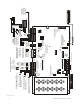
MS-9600 Basic System Connections
Notification Appliance Circuits
2 Programmable Relays &
1 Fixed Trouble Relay
EIA-232
to printer or
personal computer
SLC Loop
OR
2
1
4
3
6
5
Connector for Optional 2nd
Signalling Line Circuit Module
Flash Memory Load Enable Switch.
UP is normal position for switch.
DOWN position allows loading of
factory software upgrades
Cut this jumper to supervise
the 4XTMF module when
installed (see JP10 & JP11)
+ +
+
B
+
B
+
B
-
B
-
A
+
A
+
A
-
A
-
shield
- -
-
NO NC C NC NO C NO NC C
Alarm* Trouble Supervisory*
Black
5 4 3 2 1
9 8 7 6
Green
White
Red
T
X
R
C
V
D
T
R
TB7 (option to DB-25)
5 4 3 2 1
25 24 23 22 21 20 19 18 17 16 15 14
9 8 7 613 12 11 10
+
-
TERM
(EIA-485)
to LCD-80F
I
N
+
O
U
T
+
I
N
-
O
U
T
-
B
+
B
-
BA
+
A
-
A
CAUTION! HIGH VOLTAGE
NC NO C
+
+
+
+
+
+
120 VAC, 60 HZ, 3.2 amps
24 VDC, 25 Amp Hour maximum
T
X
R
C
V
D
T
R
G
N
D
G
N
D
9600lay3.cdr