
User manual
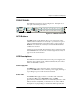

Chapter 2. Installation and Operation
61185001L1-1 MX2810 M13 User Manual 2-11
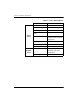
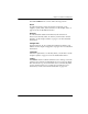
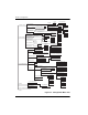
T1/E1 Status LEDs
These LEDs apply to each individual T1 or E1. Different conditions
are indicated by the state of the LED (its color and whether it
flashes, alternates color, or is on solid). The condition descriptions
vary depending on whether the LEDs represent T1s or E1s of the
active controller card or the controller card on standby. Table 2-5
provides LED definitions for the active and standby cards.
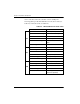
PRF
green solid Normal (All OK)
red flash (once per event) Single/Burst CV
red blinking Continuous Code Violations
red solid XCV Threshold Exceeded
(see XCV Threshold on page
3-4)
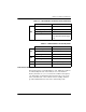
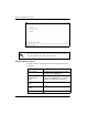
Table 2-4. LED Conditions for Standby Cards
LED State Card Condition
ACT
green blinking Normal (All OK)
amber solid Software Update in Progress
red blinking Self Test Failed
DS3
off Normal (All OK)
red blinking DS3 Failure
ALM off Normal (No Alarm)
PRF off Normal (All OK)
Table 2-3. LED Conditions for Active Cards (Continued)
LED State Card Condition