TOTAL ACCESS 600R System Manual 4200600L1#TDM 61200600L1-1A December 2002 Total Access 600R TDM
Trademarks Any brand names and product names included in this manual are trademarks, registered trademarks, or trade names of their respective holders. To the Holder of the Manual The contents of this manual are current as of the date of publication. ADTRAN reserves the right to change the contents without prior notice.
About this Manual This manual provides a complete description of the Total Access 600R system and system software. The purpose of this manual is to provide the technician, system administrator, and manager with general and specific information related to the planning, installation, operation, and maintenance of the Total Access 600R. This manual is arranged so that needed information can be quickly and easily found. The following is an overview of the contents. Section 1 System Description . . . . . . . .
Revision History This is the first issue of this manual. 4 © 2002 ADTRAN, Inc.
Notes provide additional useful information. Cautions signify information that could prevent service interruption. Warnings provide information that could prevent damage to the equipment or endangerment to human life. Safety Instructions When using your telephone equipment, please follow these basic safety precautions to reduce the risk of fire, electrical shock, or personal injury: 1.
FCC regulations require that the following information be provided in this manual: 1. This equipment complies with Part 68 of FCC rules. On the back of the equipment housing is a label showing the FCC registration number and ringer equivalence number (REN). If requested, provide this information to the telephone company. 2. If this equipment causes harm to the telephone network, the telephone company may temporarily discontinue service.
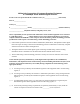
• • The affidavit shall affirm that either no encoded analog content or billing information is being transmitted or that the output of the device meets Part 68 encoded analog content or billing protection specifications. End user/customer will be responsible for filing an affidavit with the local exchange carrier when connecting unprotected customer premise equipment (CPE) to 1.544 Mbps or subrate digital services.
Affidavit for Connection of Customer Premises Equipment to 1.544 Mbps and/or Subrate Digital Services For the work to be performed in the certified territory of ___________________ (telco name) State of ________________ County of ________________ I, _______________________ (name), ____________________________________ (business address), ____________________ (telephone number) being duly sworn, state: I have responsibility for the operation and maintenance of the terminal equipment to be connected to 1.
I agree to provide ______________________ (telco’s name) with proper documentation to demonstrate compliance with the information as provided in the preceding paragraph, if so requested.
Federal Communications Commission Radio Frequency Interference Statement This equipment has been tested and found to comply with the limits for a Class A digital device, pursuant to Part 15 of the FCC Rules. These limits are designed to provide reasonable protection against harmful interference when the equipment is operated in a commercial environment.
Industry Canada Compliance Information Notice: The Industry Canada label applied to the product (identified by the Industry Canada logo or the “IC:” in front of the certification/registration number) signifies that the Industry Canada technical specifications were met. Notice: The Ringer Equivalence Number (REN) for this terminal equipment is supplied in the documentation or on the product labeling/markings.
Warranty and Customer Service ADTRAN will repair and return this product within ten years from the date of shipment if it does not meet its published specifications or fails while in service. For detailed warranty, repair, and return information refer to the ADTRAN Equipment Warranty and Repair and Return Policy Procedure. Return Material Authorization (RMA) is required prior to returning equipment to ADTRAN.
Customer Service, Product Support Information, and Training ADTRAN will repair and return this product if within ten years from the date of shipment the product does not meet its published specification or the product fails while in service. A return material authorization (RMA) is required prior to returning equipment to ADTRAN. For service, RMA requests, training, or more information, use the contact information given below.
Post-Sale Support Your reseller should serve as the first point of contact for support. If additional support is needed, the ADTRAN Support web site provides a variety of support services such as a searchable knowledge base, updated firmware releases, latest product documentation, service request ticket generation and trouble-shooting tools. All of this, and more, is available at: http://support.adtran.com When needed, further post-sales assistance is available by calling our Technical Support Center.
SYSTEM DESCRIPTION This section of ADTRAN’s Total Access 600R System Manual is designed for use by network engineers, planners, and designers for overview information about the Total Access 600R. It contains general information and describes the L2 protocol support, routing capability, security, and testing features. This section should be used in conjunction with Section 2, Engineering Guidelines, of this system manual. CONTENTS System Overview. . . . . . . . . . . . . . . . . . . . . . . . . . . . . . .
Section 1 System Description 16 Total Access 600R System Manual © 2002 ADTRAN, Inc.
Total Access 600R System Manual 1. Section 1 System Description SYSTEM OVERVIEW The Total Access 600R is a cost-effective T1/FT1 access router designed for small and medium businesses, branch offices and campuses. The unit provides 1.54 Mbps for dedicated Internet access or remote office connectivity. With its integrated CSU/DSU, the Total Access 600R provides wide area network access over a standard T1 or fractional T1 circuit. Multiple users can share network access over a single T1 connection.
Section 1 System Description 2. Total Access 600R System Manual FEATURES AND BENEFITS Below is a list of unit features and benefits. Configuration and Management • • • • • • • • VT100 emulation via the CRAFT port Telnet SNMP LAN and WAN status LEDs Text-based configuration file support Syslog client ICMP Ping utility Trace route utility Software Upgradeable • • TFTP download XMODEM via CRAFT port Network Interface • • • • • • • Line Rate: T1 1.
Total Access 600R System Manual Section 1 System Description Protocol Support • • • • • • • • • IP DNS TCP RIP V1, V2 and static routes UDP, UDP Relay ICMP ARP PPP Frame Relay Frame Relay • • • Support for both point-to-point and point-to-multipoint networks using up to 10 PVCs RFC 1490 Encapsulation (Multiprotocol over Frame Relay) Signaling Types: LMI, Annex D (ANSI), Annex A (Q933A), and Static (No Signal) PPP • • LCP, IPCP, BCP, CCP Van Jacobson (VJ) header compression Routing Capability • • • •
Section 1 System Description Total Access 600R System Manual Testing • • • • 20 Local Loopbacks: Line and Payload Remote Loopbacks: Line, Payload, CSU Loopbacks, and Fractional T1 loopback per ANSI T1.403-1995 (Annex B) Error Counts: ES, SES, SEF, FS, LCV, SLP, and UAS Alarm Status: Loss of signal, Red Alarm, Yellow Alarm, and Blue Alarm © 2002 ADTRAN, Inc.
ENGINEERING GUIDELINES CONTENTS Equipment Dimensions . . . . . . . . . . . . . . . . . . . . . . . . . . . . . . . . . . . . . . . . . . . . . . . . . . . . . . . . . . 22 Power Requirements . . . . . . . . . . . . . . . . . . . . . . . . . . . . . . . . . . . . . . . . . . . . . . . . . . . . . . . . . . . . 22 Reviewing the Front Panel Design . . . . . . . . . . . . . . . . . . . . . . . . . . . . . . . . . . . . . . . . . . . . . . . . . 22 Front Panel LEDs . . . . . . . . . . . . . . . . . . . . . . . .
Section 2 Engineering Guidelines 1. Total Access 600R System Manual EQUIPMENT DIMENSIONS The Total Access 600R measures 11.25” W, 7.5” D, and 2” H and comes equipped for table top or wall mount use. 2. POWER REQUIREMENTS The Total Access 600R has a maximum power consumption of 90-125 VAC 60 Hz and a maximum current draw of 300 mA. 3. REVIEWING THE FRONT PANEL DESIGN Figure 1 shows the front panel of the Total Access 600R which contains the LAN, WAN, and power LEDs.
Total Access 600R System Manual Section 2 Engineering Guidelines Table 1. Total Access 600R Front Panel LEDs (Continued) For these LEDs... This color light... Indicates that... WAN ERR Red (flashing) The T1 is down. Yellow (solid) Errors are present on the WAN link. Red (solid) Severe errors are present on the WAN link. Off WAN link is up and error-free. Green (solid) Power is supplied to the unit. Off Power is not supplied to the unit. PWR 4.
Section 2 Engineering Guidelines Total Access 600R System Manual Craft Port The CRAFT port connects to a computer or modem. The CRAFT port input provides the following functions: • Accepts input from a PC or a modem for controlling the unit. • Operates at 300, 1200, 2400, 4800, 9600, 19200, 38400, 57600, and 115200 bps. • Acts as input for either VT100 or PC control. • Acts as an interface for flash memory software downloads using XMODEM. Table 3 shows the CRAFT port pinout.
Total Access 600R System Manual Section 2 Engineering Guidelines AC Power Connection Each unit includes an auto ranging 90-125 VAC, 60 Hz power supply with a 3-prong removable cable. Connect the power supply to a standard 120 VAC, 60 Hz electrical outlet for proper operation. 5. DB-9 TO RJ ADAPTER The DB-9 to RJ adapter is used to connect a PC or VT100 terminal to the CRAFT port. The adapter pinout is shown in Table 5. Table 5.
Section 2 Engineering Guidelines 6. Total Access 600R System Manual AT-A-GLANCE SPECIFICATIONS Table 6 lists the unit specifications. Table 6. Specifications Application Feature Specification T1 Network Interface Physical Interface RJ-48C Line Rate 1.
Total Access 600R System Manual Section 2 Engineering Guidelines Table 6.
Section 2 Engineering Guidelines 28 Total Access 600R System Manual © 2002 ADTRAN, Inc.
NETWORK TURNUP PROCEDURE CONTENTS Introduction . . . . . . . . . . . . . . . . . . . . . . . . . . . . . . . . . . . . . . . . . . . . . . . . . . . . . . . . . . . . . . . . . . . . 31 Tools Required . . . . . . . . . . . . . . . . . . . . . . . . . . . . . . . . . . . . . . . . . . . . . . . . . . . . . . . . . . . . . . . . . 31 Unpack and Inspect the System . . . . . . . . . . . . . . . . . . . . . . . . . . . . . . . . . . . . . . . . . . . . . . . . . . . 31 Contents of ADTRAN Shipment . . . . . . . .
Section 3 Network Turnup Procedure 30 Total Access 600R System Manual © 2002 ADTRAN, Inc 61200600L1-1A
Total Access 600R System Manual 1. Section 3 Network Turnup Procedure INTRODUCTION This section discusses the unit installation process. 2. TOOLS REQUIRED The tools required for unit installation are: • • Screws (customer-provided for wallmount installation) Screwdriver (for wall or rackmount installation) To prevent electrical shock, do not install equipment in a wet location or during a lightning storm. During installation, power should be the last connection made.
Section 3 Network Turnup Procedure • • • • Total Access 600R System Manual 2 Mounting Brackets (P/N 3265421@C) 4 Screws (P/N 3276003003) RJ-45 to DB-9 Adapter (P/N 3196ADPT001) The Total Access 600R base unit. Customers must supply the Ethernet cable. 4.
Total Access 600R System Manual 6. Section 3 Network Turnup Procedure MOUNTING OPTIONS The Total Access 600R comes equipped for table top or wallmount use. The unit is shipped with two wall-mount brackets (P/N 326542@C) and four screws (P/N 3276003003) which the customer must attach to the base unit for wallmount use. If wallmounted, the Total Access 600R must be mounted with the LEDs pointing down or sideways as shown in the mounting instructions (P/N 64200600L1#T-19A).
Section 3 Network Turnup Procedure 34 Total Access 600R System Manual © 2002 ADTRAN, Inc 61200600L1-1A
USER INTERFACE GUIDE The User Interface Guide (UIG) section of the ADTRAN Total Access 600R System Manual is designed for use by network administrators and others who will configure and provision the system. It contains information about navigating the VT100 user interface, configuration information, and menu descriptions. SECTION INDEX Navigating the Terminal Menu . . . . . . . . . . . . . . . . . . . . . . . . . . . . . . . . . . . . . . . . . . . . . . . . . . . . . . . 38 Terminal Menu Window . . . . .
Section 4 User Interface Guide Total Access 600R System Manual Interfaces (ETH[1]) > Config. . . . . . . . . . . . . . . . . . . . . . . . . . . . . . . . . . . . . . . . . . . . . . . . . . . . . 68 Interfaces (ETH[1]) > Status . . . . . . . . . . . . . . . . . . . . . . . . . . . . . . . . . . . . . . . . . . . . . . . . . . . . . 68 L2 Protocol . . . . . . . . . . . . . . . . . . . . . . . . . . . . . . . . . . . . . . . . . . . . . . . . . . . . . . . . . . . . . . . . . . . . 69 L2 Protocol (T1[0]) .
Total Access 600R System Manual Section 4 User Interface Guide FIGURES Figure 1. Figure 2. Figure 3. Figure 4. Figure 5. Figure 6. Figure 7. Figure 8. Figure 9. Figure 10. Figure 11. Top-Level Terminal Menu Window . . . . . . . . . . . . . . . . . . . . . . . . . . . . . . . . . . . . . . . . . . . . . 38 Alternate Window View . . . . . . . . . . . . . . . . . . . . . . . . . . . . . . . . . . . . . . . . . . . . . . . . . . . . . . 39 System Info Menu . . . . . . . . . . . . . . . . . . . . . . . . . .
Section 4 User Interface Guide 1. Total Access 600R System Manual NAVIGATING THE TERMINAL MENU Log in to the unit by connecting one end of the supplied silver cable to the RJ-45 interface labeled CRAFT (located on the rear of the unit) and the other to a RJ-45 to DB-9 adapter. Connect the DB-9 (female) to a VT100 terminal or PC with VT100 emulator software. Configure the terminal settings for 9600 data rate, no parity, 8 data bits, 1 stop bit, and no flow control.
Total Access 600R System Manual Section 4 User Interface Guide Window Panes When you first start a terminal menu session, the terminal menu window is divided into left and right panes. The left pane shows the list of available submenus, while the right pane shows the contents of the currently selected submenu. You can view the terminal windows in two ways: with fields and submenus displaying horizontally across the right pane, or with fields and submenus displaying vertically down the right pane.
Section 4 User Interface Guide Total Access 600R System Manual Right Window Pane Notation The right window pane shows the contents of the currently selected menu. These contents can include both submenu items and data fields. Some submenus contain additional submenus and some data fields contain additional data fields. The following chart explains the notation used to identify these additional items. This notation... Means that...
Total Access 600R System Manual Section 4 User Interface Guide To do this... Press this key... Move between the left and right panes Tab Arrows Move to the top of a screen A Move to the bottom of a screen Z Ascend one menu level Backspace Jump to terminal mode Ctrl + T Jump to NAT menu Ctrl + N Return to Login prompt (CRAFT port connection only) Ctrl + L Return to Login prompt (CRAFT port connection only) Ctrl + S Session Management Keystrokes To do this... Press this key...
Section 4 User Interface Guide Total Access 600R System Manual To do this... Press this key... Paste the item stored in the clipboard, if the information is compatible. P You must confirm all pastes except those to a single editable field. Increment the value of certain types of fields by one when you paste information into those fields. > Decrement the value of certain types of fields by one when you paste information into those fields. < Insert a new list item.
Total Access 600R System Manual Section 4 User Interface Guide Telnet Security Levels To edit terminal menu items via Telnet, you must have a password and the appropriate security level. Table 1 describes the security levels. Table 1. Telnet Password Security Levels Security Level Description Full The user has all access to view and configure all menus (same as logging in to the CRAFT port) Support The user has access to view SYSTEM INFO.
Section 4 User Interface Guide 3. Total Access 600R System Manual MENU DESCRIPTIONS SYSTEM INFO The SYSTEM INFO menu provides basic information about the unit as well as data fields for editing information. Figure 3 displays the submenus that are available when you select this menu item. All figures in this section will be representative of A.04.01 firmware or later. 0 Figure 3. System Info Menu SYSTEM INFO > SYSTEM NAME Provides a user-configurable text string for the name of the unit.
Total Access 600R System Manual Section 4 User Interface Guide SYSTEM INFO > SYSTEM CONTACT Provides a user-configurable text string for a contact name. You can use this field to enter the name, phone number, or E-mail address of a person responsible for the unit. You can enter up to 31 alpha-numeric characters in this field, including spaces and special characters (such as an underscore). The factory default is to have no entry in the system contact field.
Section 4 User Interface Guide Total Access 600R System Manual SYSTEM CONFIG Set up the unit’s operational configuration from the SYSTEM CONFIG menu. Figure 4 shows the items included in this menu. Figure 4. System Config Menu SYSTEM CONFIG > MANAGEMENT Set up the CRAFT PORT, TELNET ACCESS, SNMP MANAGEMENT, and FDL MANAGEMENT from this menu. SYSTEM CONFIG > MANAGEMENT > CRAFT PORT Set up the CRAFT PORT parameters from this menu.
Total Access 600R System Manual Section 4 User Interface Guide The security level for the CRAFT port is always set to FULL. This gives full access to all menus. Passwords are case-sensitive and can contain up to 30 alphanumeric characters (including spaces and special characters). Table 2. Instructions for Changing Passwords Step Action 1 Select the PASSWORD field—a new PASSWORD field displays. 2 Type the new password in the ENTER field. 3 Type the new password again in the CONFIRM field.
Section 4 User Interface Guide Total Access 600R System Manual SYSTEM CONFIG > MANAGEMENT > TELNET ACCESS > ACCESS Sets ACCESS to ON or OFF. The factory default value for this parameter is ON. SYSTEM CONFIG > MANAGEMENT > TELNET ACCESS > AUTHEN METHOD Set up the Telnet authentication method from this menu. The choices are PASSWORD, RADIUS, PASSWORD/RADIUS, and RADIUS/PASSWORD.
Total Access 600R System Manual Section 4 User Interface Guide Table 3. Telnet Security Levels Security Level Description Full The user has all access to view and configure all menus (same as logging in to the CRAFT port) Support The user has read-only access to view the SYSTEM INFO menu. The user has privileges to view and change everything under the SYSTEM CONFIG menu except for the CRAFT port settings, Telnet access lists, and SNMP management communities.
Section 4 User Interface Guide Total Access 600R System Manual SYSTEM CONFIG > MANAGEMENT > SNMP MANAGEMENT Activate the SNMP management and configure the SNMP communities and traps from this menu. SYSTEM CONFIG > MANAGEMENT > SNMP MANAGEMENT > ACCESS When set to OFF, SNMP access is denied. When set to ON, the unit will respond to SNMP managers based on the configuration. The factory default is ON.
Total Access 600R System Manual Section 4 User Interface Guide SYSTEM CONFIG > MANAGEMENT > SNMP MANAGEMENT > TRAPS Sets up the trap manager name and IP from this menu. # Displays the index number in the SNMP traps table. This list allows up to 20 managers to be listed to receive traps. MANAGER NAME is the text string describing the name of the entry. It is intended for easy reference and has no bearing on the SNMP trap function. You can enter up to 31 characters in this field.
Section 4 User Interface Guide Total Access 600R System Manual SYSTEM CONFIG > MANAGEMENT > FDL MANAGEMENT > ACCEPT ALL SNMP When set to ON, SNMP gets/sets received over the FDL link are always accepted regardless of the community table. When set to OFF, the community table is searched for valid manager IP addresses and the SNMP traffic is rejected if a match is not found. Default is ON.
Total Access 600R System Manual Section 4 User Interface Guide The remaining Syslog parameters have the following level choices: FATAL (Highest priority) ALERT CRITICAL ERROR WARNING NOTICE INFO DEBUG (Lowest priority) Every log message generated by the IAD has a reporting level priority. If the message priority is lower than the configured priority for the destination log, the message is not forwarded to the syslog daemon. See RFC3164: The BSD Syslog Protocol.
Section 4 User Interface Guide Total Access 600R System Manual SYSTEM CONFIG > SYSLOG > DHCP LEVEL Minimum required level for sending DHCP log messages. SYSTEM CONFIG > SYSLOG > NTP LEVEL Minimum required level for sending NTP log messages. SYSTEM CONFIG > SYSLOG > TFTP LEVEL Minimum required level for sending TFTP log messages. SYSTEM CONFIG > SYSLOG > TELNET LEVEL Minimum required level for sending TELNET log messages.
Total Access 600R System Manual Section 4 User Interface Guide SYSTEM CONFIG > SYSLOG > CFGXFER LEVEL Minimum required level for sending configuration transfer log messages. SYSTEM CONFIG > SYSLOG > ROUTER LEVEL Minimum required level for sending router log messages. SYSTEM CONFIG > SYSLOG > NONVOL LEVEL Minimum required level for sending nonvolatile memory log messages. SYSTEM CONFIG > SYSLOG > NOKIA LEVEL (This parameter is not applicable for the Total Access 600R.
Section 4 User Interface Guide Total Access 600R System Manual SYSTEM CONFIG > SYSLOG > SELFTEST LEVEL Minimum required level for sending log messages about selftest. SYSTEM CONFIG > SYSLOG > VOICE LEVEL (This parameter is not applicable for the Total Access 600R.) SYSTEM CONFIG > SYSLOG > JETSTREAM LEVEL (This parameter is not applicable for the Total Access 600R.) SYSTEM CONFIG > SYSLOG > POTS LEVEL (This parameter is not applicable for the Total Access 600R.
Total Access 600R System Manual Section 4 User Interface Guide SYSTEM CONFIG > SYSLOG > HDLC LEVEL Minimum required level for sending low level HDLC log messages. SYSTEM CONFIG > SYSLOG > VOATM LEVEL (This parameter is not applicable for the Total Access 600R.) SYSTEM CONFIG > SYSLOG > PPPOA LEVEL (This parameter is not applicable for the Total Access 600R.) SYSTEM CONFIG > SYSLOG > FDL LEVEL Minimum required level for sending FDL log messages.
Section 4 User Interface Guide Total Access 600R System Manual SYSTEM CONFIG > NETWORK TIME > TIME ZONE All time zones are based off of Greenwich Mean Time (GMT). The choices are listed below • • • • • • • GMT GMT -5 (EASTERN) GMT -6 (CENTRAL) GMT -7 (MOUNTAIN) GMT -8 (PACIFIC) GMT -9 (ALASKA) GMT -10 (HAWAII) The factory default is GMT-6 (CENTRAL).
Total Access 600R System Manual Section 4 User Interface Guide SYSTEM UTILITY Use the SYSTEM UTILITY menu to view and set the system parameters shown in Figure 5. Figure 5. System Utility Menu SYSTEM UTILITY > UPGRADE FIRMWARE Select the firmware upgrade method and perform upgrade from this menu. SYSTEM UTILITY > UPGRADE FIRMWARE > TRANSFER METHOD The customer can update firmware when unit enhancements are released. The two methods for upgrading are XMODEM and TFTP.
Section 4 User Interface Guide Total Access 600R System Manual SYSTEM UTILITY > UPGRADE FIRMWARE > TFTP SERVER FILENAME This is required when the transfer method is TFTP. It is the case-sensitive file name which contains the upgrade code. The factory default is no entry in the TFTP SERVER FILENAME field. SYSTEM UTILITY > UPGRADE FIRMWARE > TRANSFER STATUS This appears when TFTP is used. It displays the status of the transfer as it happens. Any error or success message will be displayed here.
Total Access 600R System Manual Section 4 User Interface Guide SYSTEM UTILITY > CONFIG TRANSFER > TFTP SERVER IP ADDRESS Specifies the IP address of the TFTP server. Get this number from your system administrator. If using the ADTRAN Utilities TFTP server, this number appears in the TFTP server status window. The factory default value is 0.0.0.0. SYSTEM UTILITY > CONFIG TRANSFER > TFTP SERVER FILENAME Defines the name of the configuration file that you transfer to or retrieve from the TFTP server.
Section 4 User Interface Guide Total Access 600R System Manual SYSTEM UTILITY > SYSTEM UTILIZATION > PERFORMANCE > CURRENT AVG CPU UTILIZATION CURRENT AVG CPU UTILIZATION is the running total of CPU utilization since the last clear. SYSTEM UTILITY > SYSTEM UTILIZATION > PERFORMANCE > CLEAR STATS This activator will clear all the system utilization performance stats. SYSTEM UTILITY > PING Activate the ping test and define the ping packet characteristics from this menu.
Total Access 600R System Manual Section 4 User Interface Guide SYSTEM UTILITY > PING > % LOSS Percentage loss based on ping returned from host (read-only). SYSTEM UTILITY > TRACEROUTE Utility program used to trace a data path to a final destination. SYSTEM UTILITY > TRACEROUTE > TRACE TARGET Specifies the IP address of the remote system to trace the routes to.
Section 4 User Interface Guide Total Access 600R System Manual INTERFACES Use the INTERFACES menu to view and configure parameters for the T1 and Ethernet interfaces as shown in Figure 6. Figure 6. Interfaces Menus INTERFACES (T1[0]) View the T1 interface status and configure T1 parameters from this menu. The 0 in T1[0] represents a physical port. The T1 physical port is always 0. INTERFACES (T1[0]) > CONFIG Configure the various T1 parameters and enable/disable loopbacks from this menu.
Total Access 600R System Manual Section 4 User Interface Guide INTERFACES (T1[0]) > CONFIG > FORMAT This sets the frame format for the T1 interface. The setting must match the frame format of the circuit to which the interface is connected. Choices are ESF, SF, SLC96 ALARM-16, and SLC96 ALARM-13. Extended Superframe (ESF) provides a non-disruptive means of full-time monitoring on the facility datalink (FDL). Default is ESF. SF is equivalent to the D4 frame format.
Section 4 User Interface Guide Total Access 600R System Manual INTERFACES (T1[0]) > STATUS > PERFORMANCE > ES ES (Errored Second) - For ESF mode, an errored second is defined as a second with one or more Path Code Violations (PCVs), or one or more Out of Frame (OOF) defects, or one or more Controlled Slip events, or a detected AIS (blue alarm) defect. For D4 (SF) mode, the presence of Bipolar Violations (BPVs) also triggers an errored second.
Total Access 600R System Manual Section 4 User Interface Guide INTERFACES (T1[0]) > STATUS > ALARMS > CURRENT ALARMS Displays the current alarms on the T1 interface. An asterisk in a field indicates that an alarm is active. LOS Loss of Signal. No signal detected on port interface. RED Not able to frame data received on the port. Alternately referred to as Out of Frame (OOF). YELLOW Remote alarm indicator (RAI) being received on port.
Section 4 User Interface Guide Total Access 600R System Manual INTERFACES (T1[0]) > TEST > TEST STATUS Indicates whether a test is in progress. INTERFACES (ETH[1]) View the Ethernet interface status and configure the Ethernet parameters from this menu. The 1 in ETH[1] represents a physical port. The Ethernet physical port is always 1. INTERFACES (ETH[1]) > CONFIG Enable the AUTONEGOTIATION and configure the Ethernet rate from this menu.
Total Access 600R System Manual Section 4 User Interface Guide INTERFACES (ETH[1]) > STATUS > DATA RATE Displays the data rate present on the Ethernet interface. The possibilities are 10BASET, 100BASET, and N/A. N/A indicates the AUTONEGOTIATION is set to ON and there is no Ethernet connection. This is a read-only field. INTERFACES (ETH[1]) > STATUS > DUPLEX TYPE Displays the duplex type present on the Ethernet interface. The possibilities are FULL DUPLEX and HALF DUPLEX. This is a read-only field.
Section 4 User Interface Guide Total Access 600R System Manual L2 PROTOCOL (T1[0]) > PROTOCOL Configure the L2 Protocol mode. Choices are PPP, FRE, and AUTO. The default is AUTO. Selecting AUTO enables the Auto-config feature. Reference DLP-014, Unit Installation Using The Auto-Config Feature, for more information. L2 PROTOCOL (T1[0]) > PROTOCOL > PPP Point-to-Point Protocol (PPP) is an 8-bit serial protocol which allows a PC to connect as a TCP/IP host to a network through an asynchronous port.
Total Access 600R System Manual Section 4 User Interface Guide L2 PROTOCOL (T1[0] - PPP) > CONFIG > AUTHENTICATION The AUTHENTICATION menu contains the required parameters for the authentication of the PPP peer and for being authenticated by the PPP peer. Authentication is applied between the unit and the PPP peer as described in the AUTHENTICATION submenus. L2 PROTOCOL (T1[0] - PPP) > CONFIG > AUTHENTICATION > TX METHOD This parameter specifies how the unit is to be authenticated by the PPP peer.
Section 4 User Interface Guide Total Access 600R System Manual L2 PROTOCOL (T1[0] - PPP) > CONFIG > AUTHENTICATION > RX METHOD This parameter specifies how the unit is to be authenticated by the PPP peer. There are four possible selections. Default is NONE. NONE The connection will not allow the PPP peer to authenticate it. PAP, CHAP, OR EAP The unit will ask for EAP during the first PPP LCP negotiation and allow the PPP peer to negotiate down to CHAP or PAP.
Total Access 600R System Manual Section 4 User Interface Guide L2 PROTOCOL (T1[0] - PPP) > CONFIG > PPP > FORCE PEER IP ADDRESS This option forces the PPP to negotiate the IP address entered instead of allowing the other an address to be assigned by the remote end. The default is NO. L2 PROTOCOL (T1[0] - PPP) > STATUS View the L2 PROTOCOL status for the T1 interface using the PPP protocol. L2 PROTOCOL (T1[0] - PPP) > STATUS > LCP Link Control Protocol. Reflects LCP layer active.
Section 4 User Interface Guide Total Access 600R System Manual L2 PROTOCOL (T1[0] - FRE) Configure the L2 PROTOCOL parameters and view the status of the T1 interface using Frame Relay protocol from this menu. L2 PROTOCOL (T1[0] - FRE) > CONFIG Configure the L2 PROTOCOL parameters for the T1 interface using the Frame Relay protocol. L2 PROTOCOL (T1[0] - FRE) > CONFIG > MAINTENANCE PROTOCOL The Frame Relay maintenance protocol is used on the WAN port.
Total Access 600R System Manual Section 4 User Interface Guide entry that has 0 in the DLCI field. This entry is considered the default entry to use when no match occurs. If this default entry is not present, the unit falls back to using IARP to determine the protocols to use with that particular virtual circuit. If a static maintenance protocol is used, at least one DLCI mapping must be specified. To insert a new profile, press the I key when over the Num column.
Section 4 User Interface Guide Total Access 600R System Manual L2 PROTOCOL (T1[0] - FRE) > STATUS View the L2 Protocol status for the T1 interface using the Frame Relay protocol. L2 PROTOCOL (T1[0] - FRE) > STATUS > PORT View the Frame Relay statistics on the WAN port. L2 PROTOCOL (T1[0] - FRE) > STATUS > PORT > PORT INDEX Integer used for identifying DLCIs on an interface. A single DLCI will always be port index 0. Subsequent DLCIs will have incrementing port indices.
Total Access 600R System Manual Section 4 User Interface Guide L2 PROTOCOL (T1[0] - FRE) > STATUS > PORT > DROP INVALID DLCI Number of frames received that had illegal DLCIs. L2 PROTOCOL (T1[0] - FRE) > STATUS > PORT > CLEAR STATS Selecting this activator will clear the port Frame Relay Statistics. L2 PROTOCOL (T1[0] - FRE) > STATUS > PVC'S View the Frame Relay status on a per-PVC basis. L2 PROTOCOL (T1[0] - FRE) > STATUS > PVC'S > DLCI The DCLI number identifies the virtual circuit being monitored.
Section 4 User Interface Guide Total Access 600R System Manual L2 PROTOCOL (T1[0] - FRE) > STATUS > PVC'S > CR COUNT Number of packets received on this DLCI with the command response (CR) bit set. L2 PROTOCOL (T1[0] - FRE) > STATUS > PVC'S > BECN COUNT Number of packets received on this DLCI with the Backward Explicit Congestion Notification (BECN) bit set.
Total Access 600R System Manual Section 4 User Interface Guide L2 PROTOCOL (T1[0] - AUTO) > STATUS > TX PKTS Number of packets transmitted out of the WAN port. L2 PROTOCOL (T1[0] - AUTO) > STATUS > RX PKTS Number of packets received on the WAN port. L2 PROTOCOL (T1[0] - AUTO) > STATUS > TX BYTES Number of bytes transmitted out of the WAN port. L2 PROTOCOL (T1[0] - AUTO) > STATUS > RX BYTES Number of bytes received out the WAN port.
Section 4 User Interface Guide Total Access 600R System Manual L2 PROTOCOL (ETH[1]) > STATUS View the L2 Protocol statistics for the 10/100BASET Ethernet port from this menu. L2 PROTOCOL (ETH[1]) > STATUS > TX PACKETS Total number of packets transmitted out the Ethernet port. L2 PROTOCOL (ETH[1]) > STATUS > RX PACKETS Total number of packets received from the Ethernet port. L2 PROTOCOL (ETH[1]) > STATUS > TX ERRORS Total number of transmit errors encountered on Ethernet port.
Total Access 600R System Manual Section 4 User Interface Guide L2 PROTOCOL (ETH[1]) > STATUS > CLEAR COUNTS Selecting this activator clears all the Ethernet stats. BRIDGE Configure the bridge parameters and view bridging statistics from this menu as shown in Figure 8. Figure 8. Bridge Menu BRIDGE > CONFIG Configure the interfaces and bridge table parameters from this menu. BRIDGE > CONFIG > INTERFACES (T1[0]) Configure the T1 interface bridging parameters from this menu.
Section 4 User Interface Guide Total Access 600R System Manual BRIDGE > CONFIG > INTERFACES (T1[0]) > SUB-INTERFACE The T1 sub-interface is PPP [0.0] if the L2 PROTOCOL is set for PPP. The [0.0] represents the T1 physical and logical ports, respectively. This is a read-only field. The T1 sub-interface is FRE [0.X] if the L2 PROTOCOL is set for FRAME RELAY. The [0.X] represents the T1 physical and logical ports, respectively. The T1 physical port is always 0.
Total Access 600R System Manual Section 4 User Interface Guide BRIDGE > STATUS > BRIDGE TABLE > TTL Time to Live (TTL) is the number of seconds until the address is removed from the table. This is a read-only field. ROUTER Configure the router parameters and view routing statistics from this menu as shown in Figure 9. Figure 9. Router Menu ROUTER > CONFIG Configure the interfaces, routes, DHCP Server, and UDP Relay options from this menu.
Section 4 User Interface Guide Total Access 600R System Manual The Ethernet port will always appear in the ROUTER > CONFIG > INTERFACES table regardless of the L2 Protocol mode setting. ROUTER > CONFIG > INTERFACES (ETH[1]) > SUB-INTERFACE The Ethernet sub-interface is 802.3[1.0]. The [1.0] represents the Ethernet physical and logical ports, where 1 is the physical port and 0 is the logical port assigned to the Ethernet interface. This is a read-only field.
Total Access 600R System Manual Section 4 User Interface Guide DIRECTION Allows the direction at which RIP advertisements are sent and received to be specified. TX AND RX (DEF) RIP advertisements are periodically transmitted and are listened to on this port. TX ONLY RIP advertisements are periodically transmitted but are not listened to on this port. RX ONLY RIP advertisements are listened to on this port but are not transmitted on this port. V2 SECRET Enter the secret used by RIP version 2 here.
Section 4 User Interface Guide Total Access 600R System Manual ROUTER > CONFIG > INTERFACES (T1[0]) Configure the T1 interface parameters from this menu. The 0 in T1[0] represents a physical port. The T1 physical port will always be 0. The T1 interface will not appear in the ROUTER > CONFIG > INTERFACES table if the L2 PROTOCOL MODE is set for BRIDGE ALL.
Total Access 600R System Manual Section 4 User Interface Guide ADDRESS MODE This option determines how the WAN interface receives its IP address. USER SPECIFIED is the normal mode of operation. • • • • • The choices are USER SPECIFIED (default) and IPCP ASSIGNED if the L2 PROTOCOL is set to PPP. The choices are USER SPECIFIED (default), IARP, and DHCP CLIENT if the L2 PROTOCOL is set to FRAME RELAY. IARP can be used to learn the far-end IP address.
Section 4 User Interface Guide Total Access 600R System Manual MTU (This option is not available if the L2 PROTOCOL is set to PPP.) The Maximum Transmission Unit (MTU) is the largest possible data unit that can be transmitted. The range is 64 to 1500. The default is 1500. NAT The unit can perform Network Address Translation (NAT). This feature is most widely used when connecting to the Internet. The Ethernet network can consist of private network numbers.
Total Access 600R System Manual Section 4 User Interface Guide PUBLIC ADDRESS MODE (This option is only available when NAT PORT TRANSLATION is enabled.) The public IP address used for this translation entry can be the NAPT IP address assigned to the link or can be specified. You specify an address to direct packets with certain protocols to different servers. Choices are NAPT ADDR and SPECIFIED. Default is NAPT ADDR.
Section 4 User Interface Guide Total Access 600R System Manual PRIVATE ADDRESS MODE (This option is only available when NAT PORT TRANSLATION is enabled.) The private IP address can be specified to steer certain protocols and ports to specific servers in the private network. Likewise, internal hosts can be steered to certain servers on the public network. A new request from the public network matching this entry’s public parameters will be dropped if this mode is set to ANY INTERNAL.
Total Access 600R System Manual Section 4 User Interface Guide SERV ADDR (This option is only available when NAT PORT TRANSLATION is enabled.) This is the destination of the packet. PROTO (This option is only available when NAT PORT TRANSLATION is enabled.) This shows the protocol used (TCP, UDP, ICMP, etc.). PRIV PORT (This option is only available when NAT PORT TRANSLATION is enabled.) This is the private port used for the entry.
Section 4 User Interface Guide Total Access 600R System Manual RIP Routing Information Protocol (RIP) is based on the shortest path (hops) between two IP addresses on a network. Each router maintains and broadcasts a routing table of known addresses/routes. VERSION The RIP protocol can be specified per DLCI. The possible selections are OFF (default) (meaning no RIP packets are listened to or sent), V1 (RIP version 1), or V2 (which is RIP version 2).
Total Access 600R System Manual Section 4 User Interface Guide ROUTER > CONFIG > ROUTES > STATIC ROUTES Use this menu to enter static routes to other networks. NUM Displays the index number in the static route table. ACTIVE Adds this static route entry to the IP routing table when set to YES and removes it (if it was previously added) if set to NO. Default is NO. IP ADDRESS The IP address of the host or network address of the device being routed to. Default is 0.0.0.0.
Section 4 User Interface Guide Total Access 600R System Manual ROUTER > CONFIG > DHCP SERVER > DHCP RENEWAL TIME (HOURS) The number of hours that the DHCP server should allow the device to keep its previous IP assignment, before it is required to send a new DHCP request. The default is 15 HOURS. ROUTER > CONFIG > DHCP SERVER > DOMAIN NAME Text string used to represent the domain name used by the unit.
Total Access 600R System Manual Section 4 User Interface Guide UDP PORT TYPE The choices are STANDARD (def) and SPECIFIED. The following standard UDP protocols are relayed when set: DHCP, TFTP, DNS, NTP (Network Time Protocol, port 123), NBNS (NetBios Name Server, port 137), NBDG (NetBIOS Datagram, port 138), and BootP. When SPECIFIED is set, the UDP port (1 to 65535) can be specified in the UDP Port columns (up to three per server). UDP PORT 1, 2, 3 Used for specifying UDP ports to be relayed.
Section 4 User Interface Guide Total Access 600R System Manual ROUTER > STATUS > IP ROUTES > FLAGS Important tags associated with this route entry H route is a host route G route is a gateway route S static route, or learned via IPCP, IARP, DHCP R1 learned from RIP Version 1 R2 learned from RIP Version 2 I route learned from an ICMP redirect C directly connected interface P route is private and is not advertised with RIP T route is to a triggered port (updates only when table changes) U
Total Access 600R System Manual Section 4 User Interface Guide DEFAULT TTL The default value inserted into the Time-To-Live field of the IP header of datagrams originated at this unit, whenever a TTL value is not supplied by the transport layer protocol. IP DATAGRAMS RECEIVED The total number of input datagrams received from interfaces, including those received in error.
Section 4 User Interface Guide Total Access 600R System Manual ERRORFREE DISCARDS The number of output IP datagrams for which no problem was encountered to prevent their transmission to their destination, but which were discarded (e.g., for lack of buffer space). Note that this counter would include datagrams counted in TOTAL FORWARDED DATAGRAMS if any such packets met this (discretionary) discard criterion.
Total Access 600R System Manual Section 4 User Interface Guide DISCARDED ROUTING ENTRIES A packet the unit couldn't route. CLEAR COUNTS Setting this activator clears the IP Statistics. ROUTER > STATUS > IP STATS > ICMP ICMP MESSAGES RECEIVED The total number of ICMP messages the unit received. Note that this counter includes all those counted by ICMP SPECIFIC ERRORS.
Section 4 User Interface Guide Total Access 600R System Manual ICMP TIMESTAMP REQUEST MSGS RCVD The number of ICMP Timestamp (request) messages received. ICMP TIMESTAMP REPLY MSGS RCVD The number of ICMP Timestamp Reply messages received. ICMP ADDRESS MASK REQUEST MSGS RCVD The number of ICMP Address Mask Request messages received. ICMP ADDRESS MASK REPLY MSGS RCVD The number of ICMP Address Mask Reply messages received.
Total Access 600R System Manual Section 4 User Interface Guide ICMP ECHO REQUEST MSGS SENT The number of ICMP Echo (request) messages sent. ICMP ECHO REPLY MSGS SENT The number of ICMP Echo Reply messages sent. ICMP TIMESTAMP REQUEST MSGS SENT The number of ICMP Timestamp (request) messages sent. ICMP TIMESTAMP REPLY MSGS SENT The number of ICMP Timestamp Reply messages sent. ICMP ADDR MASK REQUEST MSGS SENT The number of ICMP Address Mask Request messages sent.
Section 4 User Interface Guide Total Access 600R System Manual UDP DATAGRAMS SENT The total number of UDP datagrams sent from this unit. CLEAR COUNTS Selecting this activator clears the UDP statistics. ROUTER > STATUS > IP STATS > UDP TABLE View the UDP table statistics from this menu. LOCAL IP ADDRESS The destination IP address of the packet. PORT The destination UDP port of the packet. ROUTER > STATUS > IP STATS > TCP View the TCP statistics from this menu.
Total Access 600R System Manual Section 4 User Interface Guide ACTIVE TCP CONNECTIONS The number of times TCP connections have made a direct transition to the SYN-SENT state from the CLOSED state. TCP PASSIVE CONNECTIONS The number of times TCP connections have made a direct transition to the SYN-RCVD state from the LISTEN state.
Section 4 User Interface Guide Total Access 600R System Manual ROUTER > STATUS > IP STATS > TCP CONNS View the TCP Conns Statistics from this menu. This table shows the different states of each TCP connection. STATE The possible states are FREE, CLOSED, LISTEN, SYNC SENT, SYNC RECEIVED, ESTABLISHED, FINWAIT1, FINWAIT2, CLOSEWAIT, LASTACK, CLOSING, and TIMEWAIT. LOCAL IP ADDRESS Local IP address of the TCP connection. LOCAL PORT Local port of the TCP connection.
Total Access 600R System Manual Section 4 User Interface Guide SECURITY Configure the SECURITY FILTERS and RADIUS SERVER parameters from this menu as shown in Figure 10. Figure 10. Security Menu SECURITY > FILTERS Configure the filter characteristics from this menu. SECURITY > FILTERS > FILTER DEFINES The unit can filter packets based on certain parameters within the packet. The method used by the unit allows the highest flexibility for defining filters and assigning them to a PVC or PPP link.
Section 4 User Interface Guide Total Access 600R System Manual NUM Indicates the entry number in the MAC Filter Defines table. NAME Identifies the filter entry. Default is no entry in NAME field. SRC ADDR 48-bit MAC source address used for comparison. Values are in hexadecimal format. Default is 00:00:00:00:00:00. SRC MASK Bits in the MAC source address which are compared. Values are in hexadecimal format. Default is 00:00:00:00:00:00. DEST ADDR 48-bit MAC destination address used for comparison.
Total Access 600R System Manual Section 4 User Interface Guide OFFSET Offset from beginning of packet of where to start the pattern comparison. Default is 0. PATTERN 64 bits used for comparison. Values are in hexadecimal format. Default is 00:00:00:00:00:00:00:00. MASK Bits in the pattern to be compared. Values are in hexadecimal format. Default is 00:00:00:00:00:00:00:00.
Section 4 User Interface Guide Total Access 600R System Manual SRC PORT COMP Type of comparison that is performed. Default is NONE. = means ports equal to not = means port not equal to > means port greater than < means port less than None - means the source port is not compared DEST PORT IP destination port number used for comparison. Value is in decimal format. Range: 0 TO 65535. Default is 0. DEST PORT COMP Type of comparison that is performed. Default is NONE.
Total Access 600R System Manual Section 4 User Interface Guide SECURITY > FILTERS > INTERFACES The unit can block packets in and out of an interface by use of the filters. They are set up in two steps: 1) define the types of packets that would be of interest in the SECURITY > FILTERS > FILTER DEFINES menu, and 2) set up the filter type and combination of defines that will cause a packet block. SECURITY > FILTERS > INTERFACES (T1[0]) Define the filters for the T1 interfaces from this menu.
Section 4 User Interface Guide Total Access 600R System Manual # Indicates the entry number in the In Exceptions table. ACTIVE Turns this entry active when set to YES. Default is NO. TYPE Selects the filter define list to reference (default is MAC): MAC from the SECURITY/FILTERS/FILTER DEFINES/MAC FILTER DEFINES list. PATTERN from the SECURITY/FILTERS/FILTER DEFINES/PATTERN FILTER DEFINES list. IP from the SECURITY/FILTERS/FILTER DEFINES/IP FILTER DEFINES list.
Total Access 600R System Manual Section 4 User Interface Guide DISABLE (DEF) Turns off packet output filtering. No outgoing packets are blocked. BLOCK ALL All outgoing packets to the WAN are blocked except as defined in the SECURITY > FILTERS > INTERFACES > SETUP > OUT EXCEPTIONS list. FORWARD ALL No outgoing packets to the WAN are blocked except as defined in the SECURITY > FILTERS > INTERFACES > SETUP > OUT EXCEPTIONS list.
Section 4 User Interface Guide Total Access 600R System Manual END the last filter to combination. AND logically AND this filter with the next filter in the list. OR logically OR this filter with the next filter in the list. SECURITY > FILTERS > INTERFACES (ETH[1]) Define the filters for the Ethernet interface from this menu. SECURITY > FILTERS > INTERFACES (ETH[1]) > SUB-INTERFACE The Ethernet sub-interface is 802.3[1.0]. This is a read-only field.
Total Access 600R System Manual Section 4 User Interface Guide MAC from the SECURITY > FILTERS > FILTER DEFINES > MAC FILTER DEFINES list. PATTERN from the SECURITY > FILTERS > FILTER DEFINES > PATTERN FILTER DEFINES list. IP from the SECURITY > FILTERS > FILTER DEFINES > IP FILTER DEFINES list. FILTER LIST NAME Selects between filters defined in the list. Default is no entry in filter list name.
Section 4 User Interface Guide Total Access 600R System Manual ACTIVE Turns this entry active when set to YES. Default is NO. TYPE Selects the filter define list to reference (default is MAC): MAC from the SECURITY > FILTERS > FILTER DEFINES > MAC FILTER DEFINES list. PATTERN from the SECURITY > FILTERS > FILTER DEFINES > PATTERN FILTER DEFINES list. IP from the SECURITY > FILTERS > FILTER DEFINES > IP FILTER DEFINES list. FILTER LIST NAME Selects between filters defined in the list.
Total Access 600R System Manual Section 4 User Interface Guide SECURITY > RADIUS SERVER > SERVER 3 This is the IP address of the third RADIUS SERVER the unit should attempt to communicate with when authenticating a Telnet session. Default is 0.0.0.0. SECURITY > RADIUS SERVER > UDP PORT This is the UDP port the unit should use when communicating with the RADIUS SERVER. The default is 1812, which is the commonly used port.
Section 4 User Interface Guide Total Access 600R System Manual DS0 MAPS The DS0 MAPS menu allows you to map data and voice ports to the network T1 time slots. You may edit either of the two maps at any time. If you make changes to the current map, only those DS0s that have changed will be updated (unchanged DS0s will not be affected). The DS0 menu is shown in Figure 11. Figure 11. DS0 Maps Menu. DS0 MAPS > ACTIVE MAP Activates one of the two dedicated maps (MAP 1 or MAP 2). Default is MAP 1.
Total Access 600R System Manual Section 4 User Interface Guide DS0 MAPS > EDIT/VIEW MAP 1 > DS0 Displays the network T1 time slot to be assigned. DS0 MAPS > EDIT/VIEW MAP 1 > SERVICE When you select this option, a list of all of the slots and the modules displays. The first option is OPEN, which unassigns the slot if selected. Use TA 600R to map network timeslots to the router. Pick the appropriate SERVICE and press . Default is OPEN.
Section 4 User Interface Guide Total Access 600R System Manual DS0 MAPS > EDIT/VIEW MAP 2 > RBS Robbed Bit Signaling. The RBS parameter remains at N/A for the TA 600R because RBS is not applicable to data communications. 118 © 2002 ADTRAN, Inc.
Total Access 600R System Manual Section 4 User Interface Guide Appendix A. Configuring the Unit for Routing Initial Setup Before the unit can be configured for routing, the DS0s must be mapped. DS0 Mapping DS0 Mapping Instructions Step 1. Action From the Main menu, select DS0 MAPS. Verify that the ACTIVE MAP is set to either MAP 1 or MAP 2. This is the map that is actively running on the unit. The unit has the ability to store two maps. 2.
Section 4 User Interface Guide Total Access 600R System Manual IP Routing After completing the DS0 mapping, there are three remaining steps required for the unit to be used for IP Routing: (1) Ethernet Interface Configuration, (2) T1 Interface Configuration, and (3) Default Gateway Configuration. All of these procedures are described in the pages that follow.
Total Access 600R System Manual Section 4 User Interface Guide Router T1 Interface Setup Before configuring the Router T1 Interface, choose L2 PROTOCOL and select PPP, FRE, or AUTO. Setup instructions for the PPP and FRE are described on the following pages. For information on setting the L2 PROTOCOL to AUTO, reference DLP-014, Unit Installation Using The Auto-Config Feature.
Section 4 User Interface Guide Total Access 600R System Manual Router T1 Interface Setup Instruction when L2 Protocol = Frame Relay (FRE) (required if the unit is to be used for Frame Relay IP Routing on the WAN interface) Step Action 1 From the Main menu, select L2 PROTOCOL and press ENTER. 2 Set the T1 [0] interface protocol to FRE. 3 Press Enter on the CONFIG [+] option. 4 Set the MAINTENANCE PROTOCOL to ANNEX D (ANSI), ANNEX A (q 933a), LMI, OR STATIC (no sig).
Total Access 600R System Manual Section 4 User Interface Guide Router T1 Interface Setup Instructions - IP Routing with NAT Step Action 1 The NAT menu is found under ROUTER >CONFIG >INTERFACES (T1 [0]) > SETUP. The NAT menu can be easily accessed by pressing . The T1 interface will not appear if a DLCI is not entered in the DLCI mapping table (L2 PROTOCOL T1[0]-FRE > CONFIG > DLCI MAPPING) when the L2 Protocol is set to Frame Relay (FRE). 2 From the NAT menu, set PORT TRANSLATION to ENABLED.
Section 4 User Interface Guide Total Access 600R System Manual Default Gateway Setup In A.04 TDM code, the default gateway is for the entire unit, not just for the Ethernet Port. Default Gateway Setup Instructions 124 1 From the Main menu, select ROUTER, select CONFIG, and select ROUTES. 2 Press Enter on the DEFAULT GATEWAY and set the corresponding IP address for the DEFAULT GATEWAY. © 2002 ADTRAN, Inc.
Total Access 600R System Manual Section 4 User Interface Guide Appendix B. Configuring the Unit for Bridging Initial Setup Before the unit can be configured for bridging, DS0s must be mapped. Reference the DS0 Mapping section on page 119. Setting up Bridging Options If the unit will be used for bridging, continue with the steps below. Bridging Bridging is supported by the PPP and Frame Relay protocols. The following procedures describe the bridging configuration for those two protocols.
Section 4 User Interface Guide Total Access 600R System Manual Frame Relay Bridging Setup Instructions 1 From the Main menu, select L2 PROTOCOL (T1[0])>PROTOCOL and select FRE. 2 Select CONFIG and press . 3 Set the MAINTENANCE PROTOCOL TO ANNEX D (ANSI), ANNEX A (q933a), LMI, or STATIC (NO SIG). The MAINTENANCE PROTOCOL should be set based on the Frame Relay switch. 126 4 Select DLCI MAPPING and press . Then select MODE and select BRIDGE ALL for all DLCIs which will use bridging.
DETAIL LEVEL PROCEDURES DLP-001 Connecting the Terminal or PC to the CRAFT Port .............................................................129 DLP-002 Logging in to the System ......................................................................................................131 DLP-003 Adding/Removing Telnet Users and Changing Password Security Levels ..........................135 DLP-004 Setting Ethernet IP Parameters .............................................................................
Section 5 DLP-Index 128 Total Access 600R System Manual © 2002 ADTRAN, Inc.
CONNECTING THE TERMINAL OR PC TO THE CRAFT PORT Introduction Provisioning is facilitated by a series of intuitive menus that are accessible on a computer screen. Connecting either a VT100 terminal or a PC emulating a VT100 terminal to the CRAFT port on the rear of the unit allows access to the menus and management features of the unit. This section specifies how to connect the VT100 terminal or PC to the unit. Access to the unit is through the port labeled CRAFT, an RJ-45 connector on the back of the unit.
Section 5 DLP-001 Total Access 600R System Manual DLP-001 Perform Steps Below in the Order Listed 1. Connect a VT100 terminal to the unit. • • • Set the parameters of the VT100 terminal to: – 9600 baud rate – 8 data bits – No parity – 1 stop bit – No flow control If the terminal has a parallel setting, disable it and use serial port. Plug the RJ-45 male end of the data cable into the CRAFT port on the rear of the unit by using the ADTRAN-proprietary DB-9 to RJ-45 adapter.
LOGGING IN TO THE SYSTEM Introduction Once connected to the unit via either a VT100 terminal or PC configured as a VT100 terminal, it is necessary to log in to the system to gain access to the management and provisioning functions. This DLP provides specific steps for logging in to the system and accessing the various management and provisioning functions. Prerequisite Procedures Complete DLP-001, Connecting the Terminal or PC to the CRAFT Port, before logging in to a unit.
Section 5 DLP-002 Total Access 600R System Manual DLP-002 Perform Steps Below in the Order Listed 1. After connecting to the system, a blank screen will appear. Pressing any key will display the login screen shown below. The cursor will blink at the LOGIN field, waiting for a password to be entered. 2. At the LOGIN field, enter the password for the unit. Passwords are case sensitive. There is not a manufacturer’s password by default. Press to enter the menu.
Total Access 600R System Manual Section 5 DLP-002 3. Upon entering the correct password, the MAIN MENU is displayed as shown below. You are now logged in to the menu system. CONTROL L or CONTROL S will return to the login prompt shown in Step 1. Follow-up Procedures Once this procedure is complete, return to the procedure which referred you to this DLP and continue with the tasks indicated there. 61200600L1-1A © 2002 ADTRAN, Inc.
Section 5 DLP-002 134 Total Access 600R System Manual © 2002 ADTRAN, Inc.
ADDING/REMOVING TELNET USERS AND CHANGING PASSWORD SECURITY LEVELS Introduction All menu items in the unit are protected by passwords of varying security levels. By assigning different passwords to different security levels, the System Administrator can control which users can view or change various menu items. You can assign multiple passwords at the same access level. This way, different users with the same access privileges can have different passwords.
Section 5 DLP-003 Total Access 600R System Manual DLP-003 Perform Steps Below in the Order Listed 1. Connect to the unit using either the 10/100BASET or CRAFT interfaces. If you are not already connected to the unit’s CRAFT interface (either with a VT100 compatible terminal or with a PC running VT100 emulation software), follow the procedure in DLP-001 Connecting the Terminal or PC to the CRAFT Port.
Total Access 600R System Manual Section 5 DLP-003 The unit contains six different password levels. The table below gives a brief description of each level. Security Level Description Full The user has all access to view and configure all menus (same as logging in to the CRAFT port). Support The user has access to view SYSTEM INFO.
Section 5 DLP-003 138 Total Access 600R System Manual © 2002 ADTRAN, Inc.
SETTING ETHERNET IP PARAMETERS Introduction If the unit is connected to an IP network for Telnet, TFTP, or SNMP management, several IP parameters must be set for the unit to communicate with the network. These parameters are described in this DLP along with the procedures for setting them. Please see your Network Administrator for the proper assignment of the following parameters: IP ADDRESS, SUBNET MASK, and DEFAULT GATEWAY.
Section 5 DLP-004 Total Access 600R System Manual DLP-004 Perform Steps Below in the Order Listed 1. Connect the unit to your VT100 system (details found in DLP-001, Connecting the Terminal or PC to the CRAFT Port). 2. Log in to the system with maximum rights (details for logging in are in DLP-002 and DLP-003). 3. From the ROUTER/CONFIG/INTERFACES (ETH[1]) menu, select the SETUP option and press . 4. Select the PRIMARY IP option and press . Select IP ADDRESS and press .
VERIFYING COMMUNICATIONS OVER AN IP LAN Introduction When an ETHERNET port is connected to a local area network (LAN), test steps must be performed on the unit to ensure that it is communicating properly over the network. This procedure outlines those steps. Prerequisite Procedures Before beginning this procedure, the unit should be physically connected to the LAN and the provisioning tasks detailed in DLP-004, Setting Ethernet IP Parameters should be complete.
Section 5 DLP-005 Total Access 600R System Manual DLP-005 Perform Steps Below in the Order Listed 1. Ascertain the unit IP address. If you do not already have the IP Address for the unit, obtain it from the Network Administrator or manually check for the address in the ROUTER/CONFIG/INTERFACES (ETH[1])/SETUP/PRIMARY IP/IP ADDRESS menu. You must log in with a security level of CONFIG, SUPPORT, or FULL to modify the IP parameters on the unit. 2. Ping the unit from a remote computer on the network.
Total Access 600R System Manual Section 5 DLP-005 Some versions of Ping will continue running until you explicitly tell them to stop. If the program does not terminate on its own, type to get the program to stop. 3. Telnet to the unit. From the same computer used in the previous step, Telnet to the unit and verify that the Telnet session is properly opened (see DLP-006, Telnetting to the Unit). Once the Telnet session is established, press to log out and close the session.
Section 5 DLP-005 144 Total Access 600R System Manual © 2002 ADTRAN, Inc.
TELNETTING TO THE UNIT Introduction If the unit is part of a management cluster connected to the local network, you may use a PC connected to the network to Telnet into the unit. This procedure details the steps which must be performed to Telnet into the unit. Prerequisite Procedures Complete DLP-004 and DLP-005 (Steps 1 and 2 only). Tools and Materials Required • • • • • • Access to a PC or other computer connected to the LAN.
Section 5 DLP-006 Total Access 600R System Manual DLP-006 Perform Steps Below in the Order Listed 1. Connect the computer to the unit’s CRAFT port as shown in DLP-001, Connecting the Terminal or PC to the CRAFT Port. 2. Log in to the unit as shown in DLP-002, Logging in to the System. 3. Select SYSTEM CONFIG, MANAGEMENT, and TELNET ACCESS. 4. Right arrow to AUTHEN METHOD and press . Select PASSWORD, RADIUS, PASSWORD/RADIUS, or RADIUS/PASSWORD and press . 5.
Total Access 600R System Manual Section 5 DLP-006 11. Press to log out of the unit. 12. From a remote computer system connected to the LAN, Telnet to the unit. Refer to the documentation of the computer system if you are unsure how to perform a Telnet. Most computers running a networked version of Microsoft Windows™ or UNIX allow a Telnet to be performed by simply typing Telnet at a command line prompt.
Section 5 DLP-006 Total Access 600R System Manual 14. Enter the password assigned in Step 7. Upon entering the correct password, the unit’s Main Menu is displayed as shown below: You are now Telnetted into the unit’s menu system. 15. When you complete your configuration changes and save the changes (when prompted), press to log out and close the session.
UPGRADING THE FIRMWARE USING XMODEM Introduction The unit supports firmware updates via the 10/100BASET port using either TFTP from a network server or the CRAFT interface using XMODEM. XMODEM is found in the VT100 terminal application in the ADTRAN Utilities package and in most PC VT100 communications software packages. This procedure outlines the steps for a successful firmware upgrade using the CRAFT interface and XMODEM software. Firmware may be obtained from the ADTRAN website at www.adtran.com.
Section 5 DLP-007 Total Access 600R System Manual DLP-007 Perform the Steps Below in the Order Listed 1. Connect to the unit using the CRAFT interface. If you are not already connected to the unit’s CRAFT interface (either with a VT100 compatible terminal or with a PC running VT100 emulation software), follow the procedure in DLP-001, Connecting the Terminal or PC to the CRAFT Port. Connecting to the CRAFT interface limits the upgrade procedure to XMODEM Only. 2. Log in to the unit.
Total Access 600R System Manual Section 5 DLP-007 Follow-up Procedures Once this procedure is complete, return to the procedure which referred you to this DLP and continue with the tasks indicated there. 61200600L1-1A © 2002 ADTRAN, Inc.
Section 5 DLP-007 152 Total Access 600R System Manual © 2002 ADTRAN, Inc.
UPGRADING THE FIRMWARE USING TFTP Introduction The unit supports firmware updates via the 10/100BASET Ethernet port using either TFTP from a network server or the CRAFT interfaces using XMODEM. The unit also supports TFTP updates across the WAN using the data/router channels. This DLP provides the steps to follow for a successful firmware upgrade using the 10/100BASET Ethernet port and a TFTP Server.
Section 5 DLP-008 Total Access 600R System Manual DLP-008 Perform Steps Below in the Order Listed For LAN Upgrades 1. Connect to the unit using the 10/100BASET interface. If you are not already connected to the unit’s 10/100BASET port using Telnet client software, use the procedure in DLP-006, Telnetting to the Unit, to connect to the unit. 2. Verify the TFTP server is running on the network. The user may ping the TFTP server from the unit to verify communication.
Total Access 600R System Manual Section 5 DLP-008 Prior to the start of the upgrade, the transfer status will display IDLE. During the TFTP upload, various status messages display in TRANSFER STATUS to indicate progress. The following table describes these messages. Message Meaning Transferring... [X KB] Indicates communication with the TFTP network server has been established and the update file is being transferred between the unit and the TFTP network server.
Section 5 DLP-008 Total Access 600R System Manual Prior to the start of the upgrade, the transfer status will display IDLE. During the TFTP upload, various status messages display in TRANSFER STATUS to indicate progress. The following table describes these messages. Message Meaning Transferring... [X KB] Indicates communication with the TFTP network server has been established and the update file is being transferred between the unit and the TFTP network server.
SAVING THE CURRENT CONFIGURATION USING TFTP Introduction The unit supports configuration transfers from the unit (via the 10/100BASET Ethernet port) to a TFTP server located on the network or a TFTP server accessible across the WAN. This DLP provides the steps to follow for a successful configuration transfer using the 10/100BASET Ethernet port and a TFTP Server.
Section 5 DLP-009 Total Access 600R System Manual DLP-009 Perform Steps Below in the Order Listed Saving Configuration using TFTP Server on Local Network 1. Connect to the unit using the 10/100BASET interface. If you are not already connected to the unit’s 10/100BASET port using Telnet client software, use the procedure in DLP-006, Telnetting to the Unit, to connect to the unit. 2. Verify the TFTP server is running on the network. A TFTP server ships as part of the ADTRAN utilities.
Total Access 600R System Manual Section 5 DLP-009 8. View CURRENT TRANSFER STATUS to verify the progress of the current transfer. During a successful transfer, you will first see DOWNLOAD: COPYING INTERNAL CONFIG, and then DOWNLOAD IN PROGRESS.... 9. When the transfer has successfully completed, IDLE displays in the CURRENT TRANSFER STATUS field. TFTP is not secure. No passwords are required for client access.
Section 5 DLP-009 160 Total Access 600R System Manual © 2002 ADTRAN, Inc.
LOADING THE CURRENT CONFIGURATION USING TFTP Introduction The unit supports configuration uploads from a unit (via the 10/100BASET Ethernet port) to a TFTP server located on the network or a TFTP server accessible across the WAN. This DLP provides the steps for a successful configuration upload using the 10/100BASET Ethernet port and a TFTP server.
Section 5 DLP-010 Total Access 600R System Manual DLP-010 Perform Steps Below in the Order Listed Loading Configuration using TFTP Server on Local Network 1. Connect to the unit using the 10/100BASET interface. If you are not already connected to the unit’s 10/100BASET port using Telnet client software, use the procedure in DLP-006, Telnetting to the Unit, to connect to the unit. 2.
Total Access 600R System Manual Section 5 DLP-010 11. After an appropriate length of time, the user may Telnet back into the unit. TFTP is not secure. No passwords are required for client access. Anyone can access files through the IP port on the server machine if they know the target file’s name. Loading Configuration using TFTP Server Accessible Across the WAN 1. Telnet into the unit using FULL or SUPPORT levels (refer to DLP-003, Adding/Removing Telnet Users and Changing Password Security Levels). 2.
Section 5 DLP-010 Total Access 600R System Manual 10. After an appropriate length of time, the user may Telnet back into the unit. TFTP is not secure. No passwords are required for client access. Anyone can access files through the IP port on the server machine if they know the target file’s name. Follow-up Procedures Once this procedure is complete, return to the procedure which referred you to this DLP and continue with the tasks indicated there. 164 © 2002 ADTRAN, Inc.
SAVING THE CURRENT CONFIGURATION USING XMODEM Introduction The unit supports configuration transfers from the unit using a VT100 terminal or terminal emulator (with XMODEM) and the CRAFT interface. This DLP provides the steps to follow for a successful configuration transfer using the CRAFT port and XMODEM.
Section 5 DLP-011 Total Access 600R System Manual DLP-011 Perform Steps Below in the Order Listed 1. Connect to the unit using the RJ-45 CRAFT interface. If you are not already connected to the unit’s CRAFT interface (either with a VT100 compatible terminal or with a PC running VT100 emulation software), follow the procedure in DLP-001, Connecting the Terminal or PC to the CRAFT Port. Connecting to the CRAFT port interface limits the config transfer procedure to XMODEM only. 2. Log in to the unit.
LOADING THE CURRENT CONFIGURATION USING XMODEM Introduction The unit supports configuration uploads from a unit using a VT100 terminal or terminal emulator (with XMODEM) and the CRAFT interface. This DLP provides the steps for a successful configuration upload using the CRAFT port and XMODEM. Prerequisite Procedures Obtain the configuration file (see for DLP-011, Loading the Current Configuration Using XMODEM, for details).
Section 5 DLP-012 Total Access 600R System Manual DLP-012 Perform Steps Below in the Order Listed 1. Connect to the unit using the RJ-45 CRAFT interface. If you are not already connected to the unit’s CRAFT interface (either with a VT100 compatible terminal or with a PC running VT100 emulation software), follow the procedure in DLP-001, Connecting the Terminal or PC to the CRAFT Port. Connecting to the CRAFT interface limits the config transfer procedure to XMODEM Only. 2. Log in to the unit.
SAVING AND LOADING TEXT CONFIGURATION USING THE TERMINAL COMMAND LINE Introduction The unit has the ability to download a text file which contains the configuration of the entire unit. This configuration may be altered in a text editor and then uploaded to the unit. This DLP will explain how to save and load the configuration.
Section 5 DLP-013 Total Access 600R System Manual DLP-013 Perform Steps Below in the Order Listed Saving the Router's Configuration 1. Establish a connection to the router with the terminal software either through the CRAFT port or via a Telnet session. 2. From the Main Menu, select SYSTEM UTILITY, then TERMINAL MODE, and then press . 3. The following screen will appear. 4. At the terminal prompt, type download and then press . The following screen will appear. 170 © 2002 ADTRAN, Inc.
Total Access 600R System Manual Section 5 DLP-013 * 5. Don’t press another key yet! 6. Enable "capture" or "logging" in the terminal software, saving it to a file on your computer. 7. Press the SPACE BAR to continue. The router will then print its configuration to the terminal screen. (With capture enabled, the terminal software will capture the configuration and write it to the file that you designated.) 8. When the configuration stops printing, end the capture.
Section 5 DLP-013 Total Access 600R System Manual Entering Commands at the Command Prompt To do this manually from the prompt, precede each instruction with a ">". After uploading, to apply and save changes, you must issue the command "save" from the prompt. The command will apply ALL changes to the unit (the same as escaping all the way out of the terminal menu). To do a save to flash only, but not apply the changes, you can go back to the menu system and press .
UNIT INSTALLATION USING THE AUTO-CONFIG FEATURE Introduction AUTO-CONFIG allows the service provider to gain initial access to a newly installed IAD while in its factory default state. This eliminates the need for a skilled technician on-site during installation, as it only requires someone to make the network interface and power connections to the IAD. After accessing the unit, the service provider remotely loads a configuration script. A fail-safe timer is then set and the configuration is saved.
Section 5 DLP-014 Total Access 600R System Manual Tools and Materials Required • • • • VT100 compatible terminal or computer with terminal emulation software (only required if unit has to be factory defaulted) Appropriate cable to connect terminal to the unit (customer provided, only required if unit has to be factory defaulted) DB-9 female to RJ-45 female adapter for connecting to the CRAFT port on the rear of the unit (only required if unit has to be factory defaulted) Silver Satin Cable for CRAFT acce
Total Access 600R System Manual Section 5 DLP-014 DLP-014 Perform Steps Below in the Order Listed 1. Verify the unit is at factory default. 2. Connect the network interface cable to the NTWK port on the rear of the unit. 3. Power up the unit. 4. The unit begins auto-detecting whether the packets received on the WAN interface are PPP LCP packets or Frame Relay signaling packets.
Section 5 DLP-014 Total Access 600R System Manual 7. Set the failsafe timer by selecting SYSTEM UTILITY>TERMINAL MODE and typing fstimer start x, (where x is in seconds) at the > prompt. Select a value for x which will allow enough time for the service provider to reconfigure the network to match the unit's new configuration and which will allow an extra 3 to 5 minutes for the unit to sync up with the network. Set the failsafe timer prior to doing the save.
A.03 TO A.04 FIRMWARE UPGRADE Introduction Until now, the Total Access 600R has been running firmware version A.03.xx. Recently, A.04.xx has been released. The development of A.04.xx code is a significant step in the evolution of the Total Access product line, as it allows all Total Access family members to share the same base code. This means that features and fixes are more easily implemented and are propagated across the product line. The two possible A.03 to A.04 upgrade paths are described in this DLP.
Section 5 DLP-015 Total Access 600R System Manual Tools and Materials Required • • • 178 VT100 compatible terminal or computer with terminal emulation software Appropriate cable to connect terminal to the unit (customer provided) DB-9 female to RJ-45 female adapter for connecting to the CRAFT port on the rear of the unit. This adapter is ADTRAN proprietary and is shipped with the unit. © 2002 ADTRAN, Inc.
Total Access 600R System Manual Section 5 DLP-015 DLP-015 Perform Steps Below in the Order Listed Upgrade From A.03 to A.03.9X (Transition Build) to A.04 1. Upgrade the firmware from A.03 to A.03.9X (Transition Build) firmware. See DLP-007 or DLP-008 for instructions on how to perform this upgrade. 2. Once the upgrade to A.03.9X is complete, immediately upgrade the unit to A.04. See DLP-007 or DLP-008 for instructions on how to perform this upgrade. Upgrading from A.03 to A.03.
Section 5 DLP-015 180 Total Access 600R System Manual © 2002 ADTRAN, Inc.
ADTRAN UTILITIES ADTRAN delivers several PC software utilities with the unit. These utilities are located on the CD-ROM that came with your shipment. They also include MIB files (located in the MIB directory). Review the readme file (Readme.txt) for the latest information about the utilities. The utilities make it easier to interface with the terminal menu and transfer configuration files to and from TFTP servers. The utilities all run on Microsoft Windows 3.1 or higher.
Section 6 ADTRAN Utilities 1. Total Access 600R System Manual TELNET UTILITY The Telnet utility delivered with the unit provides enhancements to standard Telnet programs that make it easier to work with unit options. Access the Telnet program remotely through the 10/100BASET Ethernet port. For a detailed description of how to work with the Telnet program, refer to Navigating the Terminal Menus in the User Interface Guide section of this manual.
Total Access 600R System Manual Section 6 ADTRAN Utilities Host Name Accepts and stores host names. You may enter a name, an IP address, or a domain name directly from this field. Click on the drop-down arrow to display a complete list of previously stored host names. PORT Provides several port options.
Section 6 ADTRAN Utilities Total Access 600R System Manual Options Menu Provides viewing alternatives for the terminal screen. Colors Three options change the color of the background window (BACKGROUND), bold highlights (BOLD), and text (TEXT). Local Echo Echoes each character that you enter. AutoRepeat Repeats characters you select from the keyboard, if you hold down the key. Capture Menu Provides options for capturing screen images.
Total Access 600R System Manual 2. Section 6 ADTRAN Utilities VT100 UTILITY Use the VT100 to configure a unit which is directly connected to a PC. The VT100 display is almost identical to the Telnet display. For a detailed description of how to work within the terminal menu, refer to Navigating the Terminal Menus in the User Interface Guide section of this manual. If you need help setting up the unit for a VT100 session, refer to the Detailed Level Procedures section of this manual.
Section 6 ADTRAN Utilities Total Access 600R System Manual XMODEM CRC Selects the XMODEM file transfer protocol. ASCII Cfg Files Selects ASCII transfer mode. Primarily useful for configuration transfers for the ADTRAN products. Edit Menu Identical to the Telnet EDIT MENU (see Edit Menu on page 183). Port Menu Changes serial COM PORT SETTINGS. Provides data rate settings from 300 - 57600 bps. Options Menu Provides terminal screen commands. Refresh Screen Redraws the screen.
Total Access 600R System Manual Section 6 ADTRAN Utilities About Displays version and owner information. 3. TFTP SERVER The TFTP Server utility transfers configuration files to and from a TFTP server. You can install this program on a PC running any version of Microsoft Windows. The configuration of the unit can be saved offline as a backup file. The saved file may also be used to send the same configuration to multiple units.
Section 6 ADTRAN Utilities Total Access 600R System Manual Figure 4. TFTP Server Interface Only one configuration transfer session (upload or download) may be active at a time. The TCP/IP parameters are not saved or overwritten as part of the unit’s transferred configuration to allow sending identical configurations to multiple units. When you start this program, a port is automatically opened. Server Menu Provides ENABLE, DISABLE, ABORT, and EXIT options. Enable Enables the TFTP server.
Total Access 600R System Manual Section 6 ADTRAN Utilities Help Provides on-line help and version information. Contents Opens on-line help. About Displays version and owner information. 4. STATUS FIELD This field displays general information about port and transfer status. This field is read-only. The unlabeled field in the center of the screen displays prompts about the status of active transfers, such as bytes transferred and received. 5.
Section 6 ADTRAN Utilities 190 Total Access 600R System Manual © 2002 ADTRAN, Inc.
MIB This section details the Management Information Bases (MIBs) supported, MIB Compilation Order, Traps Supported, and MIB Variables supported. CONTENTS MIBs Supported by the Total Access 600R . . . . . . . . . . . . . . . . . . . . . . . . . . . . . . . . . . . . . . . . . . . . . . 193 MIB Compilation Order . . . . . . . . . . . . . . . . . . . . . . . . . . . . . . . . . . . . . . . . . . . . . . . . . . . . . . . . . . . . . . 194 Traps Supported by the Total Access 600R . . . . . . . . . . . . . . .
Section 7 MIB 192 Total Access 600R System Manual © 2002 ADTRAN, Inc.
Total Access 600R System Manual 1. Section 7 MIB MIBs Supported by the Total Access 600R Standard RFC MIBs: RFC1573.mi2 IANAifType-MIB RFC1907.mi2 SNMPv2-MIB RFC2011.mi2 IP-MIB RFC2096.mi2 IP-FORWARD-MIB RFC2115.mi2 FRAME-RELAY-DTE-MIB RFC2493.mi2 PerfHist-TC-MIB RFC2494.mi2 DS0-MIB and DS0BUNDLE-MIB RFC2495.mi2 DS1-MIB RFC2665.mi2 EtherLike-MIB RFC2863.mi2 IF-MIB RFC3201.mi2 CIRCUIT-IF-MIB Enterprise MIBs: adtran.mi2 ADTRAN-MIB adIadSys.mi2 ADTRAN-ADIADSYS-MIB adIadRtr.
Section 7 MIB 2. Total Access 600R System Manual MIB COMPILATION ORDER IANAifType-MIB PerfHist-TC-MIB SNMPv2-MIB (if not included with SNMP manager) IF-MIB IP-MIB IP-FORWARD-MIB FRAME-RELAY-DTE-MIB DS1-MIB DS0-MIB DS0BUNDLE-MIB EtherLike-MIB CIRCUIT-IF-MIB ADTRAN-MIB ADTRAN-IADSYS-MIB ADTRAN-IADROUTER-MIB 3. TRAPS SUPPORTED BY THE TOTAL ACCESS 600R From RFC1215-MIB: coldStart linkDown linkUp authenticationFailure 194 © 2002 ADTRAN, Inc.
Total Access 600R System Manual From ADTRAN-IADSYS-MIB: Section 7 MIB adIadWanDown - 1003203 adIadWanUp - 1003204 adIadBatteryAlarmAct - 1003207 adIadBatteryAlarmDeact - 1003208 (T1 WAN interface only): adIadDs1RedAlarmON - 1003209 adIadDs1YellowAlarmON - 1003210 adIadDs1BlueAlarmON - 1003211 adIadDs1RedAlarmOFF - 1003212 adIadDs1YellowAlarmOFF - 1003213 adIadDs1BlueAlarmOFF - 1003214 adIadDs1SEF - 1003215 adIadDs1FS - 1003216 adIadDs1CRC - 1003217 adIadDs1LCV - 1003218 adIadDs1SLP - 1003219 4.
Section 7 MIB 196 Total Access 600R System Manual © 2002 ADTRAN, Inc.