
Netork Device Installation Manual


12 Section 61245207L2-5, Issue 3 61245207L2-5C
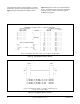
The Troubleshooting Display, shown in Figure 13,
graphically depicts a DSL circuit. The unit monitors
red, yellow, and blue alarm conditions in the circuit.
Once a fault location is suspected, the corresponding
portion of the circuit on the screen is highlighted and a
message describing the failure will appear.
Figure 13. Troubleshooting Screen
TROUBLESHOOTING DISPLAY
FT1-DP FNID
_____ _____
| | | |
| | | |
--->| | | |<---
| | | |
NET | |<===========================>| | CUST
| | | |
<---| | | |--->
| | | |
| | | |
|_____| |_____|
ALARMS: PROBLEM INDICATED:
FT1-DP CHANNEL BANK ALARM
FT1-DP RED DSL LOSS
Press “M” for Main Menu.