
Netork Device Installation Manual

2 Section 61245207L2-5, Issue 3 61245207L2-5C
C A U T I O N
C A U T I O N
!
SUBJECT TO ELECTROSTATIC DAMAGE
OR DECREASE IN RELIABILITY.
HANDLING PRECAUTIONS REQUIRED.
The FT1 Digital Subscriber Loop (DSL) local loop
operates as an independent subsystem, over a single
twisted pair. The FT1 DP communicates over this
twisted pair to the Fractional Network Interface
Device (FNID) and/or FT1 repeater listed below:
Part Number Unit Description
1242041LX ................. T400 FNID Circuit Pack
1245201LX ................. T200 FNID Circuit Pack
1242042LX ................. T400 FNID Standalone
1242050L2 .................. FT1 Repeater
1245211LX ................. FT1 Repeater
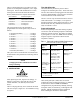
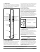
The payload between FT1 DP and FNID is
programmable from the faceplate rotary switch as
follows:
2 channels (minimum) ..................... 128 kbps
3 channels ........................................ 192 kbps
4 channels ........................................ 256 kbps
5 channels ........................................ 320 kbps
6 channels ........................................ 384 kbps
7 channels ........................................ 448 kbps
8 channels ........................................ 512 kbps
9 channels ........................................ 576 kbps
10 channels ...................................... 640 kbps
11 channels ...................................... 704 kbps
12 channels (maximum) .................. 768 kbps
The system carries a small amount of overhead used
for maintenance and performance monitoring related
functions.
NOTE
Changing the number of DS0s does not affect
unit provisioning.
2. INSTALLATION
After unpacking the unit, inspect it for damage. If
damage is noted, file a claim with the carrier, then
contact ADTRAN. See Warranty and Customer
Service.
The FT1 DP plugs directly into a Nortel DE-4E shelf.
The unit occupies a single slot. No installation wiring
is required.
Time Slot Allocation
The bandwidth may be taken by the FT1 DP in
contiguous or alternating time slots. These slots must
not have other channel cards plugged in the slots taken
by the FT1 DP bandwidth. This will cause contention
on the transmit side of the channel bank.
The FT1 will not wrap around the channels at the end
of the channel bank. For example, if n is equal to 4
channels and the FT1 DP is plugged into slot 23 of the
channel bank, then only channels 23 and 24 can be
used, not channels 1 and 2.
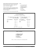
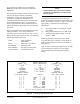
Protected Loopback
Protected Loopback prevents false latching loopback
occurrences when the latching loopback is embedded
within the customer payload. This feature is enabled
by setting SW1-8 to ON. See Table 1 for the latching
loopback sequence requirement when Protected
Loopback is enabled.
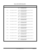
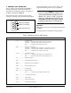
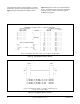
Three switch packs (SW1, SW2, SW3) are used to
configure the mode of operation for the unit. A definition
of each switch is shown in Table 2 and Table 3.
Configuration may be performed by manually selecting
each option switch, or alternatively, set through the craft
interface. Manual configuration must be performed
before installing the unit into the channel bank.
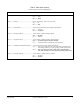
Note: Minimum of 35 TIP bytes required to disable
established latching loopback.
X = don't care bit.
Function
Sequence Byte Code # of Received
Bytes
Transition in progress
(TIP) X0111010
Loopback select
code (LSC)
X1010101 - OCU
X0110001 - CSU
X1000001 - NI
Loopback enabled
(LBE) X1010110
Far-end voice (FEV)
X1011010
Minimum of 35
TIP bytes
Minimum of 35
LSC bytes
Minimum of 100
LBE bytes
Minimum of 35
FEV bytes
Clear existing
loopbacks
Identify device
to be looped
Prepare loop,
send MAP code
after 30 bytes
Activate
loopback
Table 1. Protected Loopback Mode Requirement
T1E1.2/99-007R1 (Latching Loopback)