TEST TERM(R MON(G) ) LBK NEND(Y) FENG(G ) DS1 4 FRL7 Q11D81307 OPTIC S DS1 1 DS1 2 DS1 3 K LB CT LE SE CH ® Quad Fiber Remote (QDFR) Unit Installation and Maintenance Practice Document Number: 61181307L7-5E CLEI: M3M1100B _ _ July 2006
Quad Fiber Remote (QDFR) Unit Installation and Maintenance Practice Trademarks Front Matter Any brand names and product names included in this document are trademarks, registered trademarks, or trade names of their respective holders. To the Holder of the Document The contents of this document are current as of the date of publication. ADTRAN® reserves the right to change the contents without prior notice.
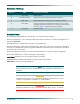
Revision History Revision Date Description of Changes A July 2005 B December 2004 C April 2005 Added QDFR Provisioning menu defaults in Table 3. D June 2006 Changed connector designation from RJ-45 to RJ-48C. Changed Transmit Level values to Output Optical Power values in Table 5. Updated document format. E July 2006 Updated CLEI. Initial release Added front panel LED information in Table 2.
Quad Fiber Remote (QDFR) Unit Installation and Maintenance Practice Training ADTRAN offers training courses on our products. These courses include overviews on product features and functions while covering applications of ADTRAN product lines. ADTRAN provides a variety of training options, including customized training and courses taught at our facilities or at customer sites. For inquiries concerning training, contact ADTRAN: Training Phone: 800-615-1176, ext.
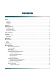
Contents General . . . . . . . . . . . . . . . . . . . . . . . . . . . . . . . . . . . . . . . . . . . . . . . . . . . . . . . . . . . . . . . . . . . . . . . . . . . . . . . . . . Description . . . . . . . . . . . . . . . . . . . . . . . . . . . . . . . . . . . . . . . . . . . . . . . . . . . . . . . . . . . . . . . . . . . . . . . . . . . . Features . . . . . . . . . . . . . . . . . . . . . . . . . . . . . . . . . . . . . . . . . . . . . . . . . . . . . . . . . . . . . . . . . . . . . . . . . . . . . .
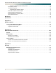
Quad Fiber Remote (QDFR) Unit Installation and Maintenance Practice Channel T1 Threshold Alarm History Screen . . . . . . . . . . . . . . . . . . . . . . . . . . . . . . . . . . . . . . . . . . Event History Screen . . . . . . . . . . . . . . . . . . . . . . . . . . . . . . . . . . . . . . . . . . . . . . . . . . . . . . . . . . . . . . . . Troubleshooting Menu . . . . . . . . . . . . . . . . . . . . . . . . . . . . . . . . . . . . . . . . . . . . . . . . . . . . . . . . . . . . . . .
Contents Figures Figure 1. Figure 2. Figure 3. Figure 4. Figure 5. Figure 6. Figure 7. Figure 8. Figure 9. Figure 10. Figure 11. Figure 12. Figure 13. Figure 14. Figure 15. Figure 16. Figure 17. Figure 18. Figure 19. Figure 20. Figure 21. Figure 22. Figure 23. Figure 24. Figure 25. Figure 26. Figure 27. Figure 28. Figure 29. Figure 30. Figure 31. Figure 32. Figure 33. Figure B-1. Figure B-2. Figure B-3. QDFR Front Panel . . . . . . . . . . . . . . . . . . . . . . . . . . . . . . . . . . . . . . . . . . .
Quad Fiber Remote (QDFR) Unit Installation and Maintenance Practice Tables Table 1. Table 2. Table 3. Table 4. Table 5. Table A-1. viii Compliance Codes . . . . . . . . . . . . . . . . . . . . . . . . . . . . . . . . . . . . . . . . . . . . . . . . . . . . . . . . . . . . . . 2 Front Panel LEDs . . . . . . . . . . . . . . . . . . . . . . . . . . . . . . . . . . . . . . . . . . . . . . . . . . . . . . . . . . . . . . . 4 QDFR Provisioning Menu Defaults . . . . . . . . . . . . . . . . . . . . . . . . . . .
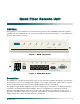
Quad Fiber Remote Unit GENERAL CH SELECT ST ) (R ) RM (G TE ON M TE K LB 1 DS DS DS 1 4 3 2 1 1 DS IC PT ) (Y ) ND (G NE ENG F O 1181307L7 S QDFR 1 This practice is an installation and maintenance guide for the ADTRAN Quad Fiber Remote (QDFR) unit. The QDFR (P/N 1181307L7) front panel is illustrated in Figure 1. The QDFR rear panel is illustrated in Figure 2. LBK Figure 1.
Quad Fiber Remote (QDFR) Unit Installation and Maintenance Practice Features The QDFR provides the following features: • Software provisionable via menu access (no onboard switches) • Front panel indicators for the following: – Optical port status – T1 status for all channels – Loopback status – Test port operation • Operation over extended temperature range of –40°C to +65°C • Optical interface consisting of a single mode transceiver module comprised of a single fiber transmitter and an SC receptacle • Op
Installation INSTALLATION C A U T I O N ! SUBJECT TO ELECTROSTATIC DAMAGE OR DECREASE IN RELIABILITY. HANDLING PRECAUTIONS REQUIRED. After unpacking the QDFR, inspect it for damage. If damage has occurred, file a claim with the carrier then contact ADTRAN Customer Service. Refer to “Appendix C, Warranty” for further information. If possible, keep the original shipping container for returning the QDFR for repair or for verification of shipping damage.
Quad Fiber Remote (QDFR) Unit Installation and Maintenance Practice Table 2.
Loop Connections LOOP CONNECTIONS The T1 loop connections are made through four RJ-48C type connectors. For each connector, transmit tip and ring are on pins 5 and 4, and receive tip and ring are on pins 2 and 1, respectively. The single-mode fiber is connected to the SC connector located on the back panel of the unit. OPERATION The Quad Fiber Remote (QDFR) Unit provides a platform to exchange data between four Tls and an optical fiber interface.
Quad Fiber Remote (QDFR) Unit Installation and Maintenance Practice PROVISIONING The QDFR provides the ability to change provisioning options. Table 3 lists the valid settings and defaults for the provisioning options. Provisioning options are set independently for each of the DS1s. Table 3.
Menu Structure MENU STRUCTURE The menu structure for the QDFR is a layered menu tree. Each layer of the menu tree is displayed as a menu or a screen. Menu A menu is a display that provides numbered selections that are used to navigate to related menus, modify provisioning information, or display information screens.
Quad Fiber Remote (QDFR) Unit Installation and Maintenance Practice MENU DESCRIPTIONS The QDFR Main Menu (Figure 4) is the access point to all other operations. The Main Menu options have several functions and submenus that identify and provide access to specific operations and parameters. Shelf: 1 Slot: 2 Unacknowledged Alarms: Total Access System mm/dd/yy hh:mm ADTRAN QDF Main Menu 1. 2. 3. 4. 5. 6. 7. 8. 9. 10. 11. 12. 13. 14.
Menu Descriptions Table 4. ADTRAN QDF Main Menu Options (Continued) Option Description Function 8 Alarm History This option displays the “Alarm History Menu” on page 20. 9 Event History This option displays the “Event History Screen” on page 21. 10 Troubleshooting This option displays the “Troubleshooting Menu” on page 22. 11 Clear PM and Alarm Histories This option displays the “Clear PM and Alarm Histories Option” on page 23.
Quad Fiber Remote (QDFR) Unit Installation and Maintenance Practice Provisioning Menu The Provisioning menu (Figure 6) is used to make provisioning changes to various options. Shelf: 1 Slot: 2 Unacknowledged Alarms: Total Access System mm/dd/yy hh:mm Provisioning 1. 2. 3. 4. 5. Channel Options Fiber PM Threshold Options T1 PM Threshold Options Copy Settings Restore Factory Defaults Selection: Figure 6.
Menu Descriptions Status Screen The Status screen (Figure 7) provides information regarding the status of the QDFR.
Quad Fiber Remote (QDFR) Unit Installation and Maintenance Practice Loopback and Test Commands Menu Loopback and Test Commands menu (Figure 9) provides several performance tests for the QDFR. Shelf: 1 Slot: 2 Total Access System mm/dd/yy hh:mm Loopback and Test Commands Loopback Status: ---------------CH1: CH2: CH3: CH4: Test Port: QDFC -----NONE NONE NONE NONE QDFR -----NONE NONE NONE NONE CH 1,Mon CH 1,Mon 1. Loopbacks 2. Loopdown All 3. Test Port (Bantam Jack) Control 4.
Menu Descriptions Test Jack Configuration Screen The Test Jack Configuration screen (Figure 11) controls the test jack, which is found on the back of the QDFR unit. This jack can “look at” a chosen port, in either direction as chosen by the user, as if it were a monitor jack (non-intrusive mode) or it can “break” a chosen port, in either direction, as if it were a equipment jack (intrusive mode).
Quad Fiber Remote (QDFR) Unit Installation and Maintenance Practice BERT Test Screen The Channel # BERT Test screen (Figure 12) performs a test with the following options: • (Re)start Pattern – Use this option to (re)start a test. • Stop Test – Use this option to manually stop a test. • Select Data Pattern – Use this option to access the Current Pattern menu (Figure 13), which is used to select the appropriate data test pattern for the desired results.
Menu Descriptions • Enter Test Timeout – This option displays the Network Timeout screen (Figure 14). The timeout can run for a specific duration by entering the hours and/or minutes, or can run indefinitely by entering 00:00. Shelf: 1 Slot: 2 Unacknowledged Alarms: Total Access System mm/dd/yy hh:mm NETWORK Timeout Screen Test Timeout(Hr:Min) = 01:00 ---------------------------1. Change Timeout *NOTE: When timeout is set to 00:00, the test will run indefinitely. Selection: Figure 14.
Quad Fiber Remote (QDFR) Unit Installation and Maintenance Practice Self-Tests Screen Selecting Self-Tests performs tests of the QDFC and QDFR, with no additional user input. If all functions pass, the “Self Test Complete” message appears (Figure 16). Shelf: 1 Slot: 2 Unacknowledged Alarms: Total Access System mm/dd/yy hh:mm SELF TEST COMPLETE QDFC : QDFR : Passed Passed Figure 16.
Menu Descriptions Performance History Channel # Menu The Performance History Channel # menu (Figure 18) displays the performance of a specific channel. From this screen, the network or customer receiver may be selected. Shelf: 1 Slot: 11 Unacknowledged Alarms: Total Access System mm/dd/yy hh:mm Performance History Channel 1 Select the Receiver of Interest 1. 2. Network Receiver (from Network) Customer Receiver (from Customer) Selection: Figure 18.
Quad Fiber Remote (QDFR) Unit Installation and Maintenance Practice The Channel Performance History of the DSX-1 Rx from the network is shown in Figure 20.
Menu Descriptions Scratch Pad, Circuit ID Menu The Scratch Pad, Circuit ID menu (Figure 22) is used to give each circuit a circuit ID name, number, or identity of the users choosing. The scratch pad can be used to make specific notes or reminders. Shelf: 1 Slot: 11 Unacknowledged Alarms: Ch Ch Ch Ch 1 2 3 4 Circuit Circuit Circuit Circuit Total Access System ID ID ID ID mm/dd/yy hh:mm = = = = Scratch Pad = (1-4). Change Circuit ID 5. Change Scratch Pad Selection: Figure 22.
Quad Fiber Remote (QDFR) Unit Installation and Maintenance Practice Alarm History Menu The Alarm History menu (Figure 23) provides the options Red, Yellow, and Blue Alarms or PM Threshold Crossing Alarms. A red alarm indicates a loss of signal or loss of framing, a yellow alarm indicates a remote alarm indication, and a blue alarm is an alarm indication signal. Shelf: 1 Slot: 11 Unacknowledged Alarms: Total Access System mm/dd/yy hh:mm Alarm History 1. 2.
Menu Descriptions Channel T1 Threshold Alarm History Screen An individual Channel T1 Threshold Alarm History screen (Figure 25) provides the errored seconds, severely errored seconds, loss of signal seconds, code violation line, and code violation path.
Quad Fiber Remote (QDFR) Unit Installation and Maintenance Practice Troubleshooting Menu The Troubleshooting menu (Figure 27) compiles information received from all facilities and equipment in the circuit and presents them in both Real-Time and 7-Day historical format. The Definitions option from this menu provides definitions of terms and acronyms.
Menu Descriptions Clear PM and Alarm Histories Option Selecting the Clear PM and Alarm Histories option from the QDF Main menu, displays the following prompt shown in Figure 29. Shelf: 1 Slot: 11 Unacknowledged Alarms: Total Access System mm/dd/yy hh:mm Adtran QDF Main Menu 1. QDF Unit Information 2. Provisioning 3. Status 4. Auto In Service 5. Loopbacks and Test 6. Performance History 7. Scratch Pad, Ckt ID 8. Alarm History 9. Event History 10. Troubleshooting 11. Clear PM and Alarm Histories 12.
Quad Fiber Remote (QDFR) Unit Installation and Maintenance Practice System PM/Screen Report Menu System PM/Screen Report menu (Figure 30) is used to generate system reports. 6. 7. 8. 9. 10. 11. 12. 13. 14. Performance History Scratch Pad, Ckt ID Alarm History Event History Troubleshooting Clear PM and Alarm Histories System PM/Screen Report Flash Upgrade Virtual Terminal Control Selection: 12 Enable data logging now.
Menu Descriptions Download QDFR via Y-Modem Menu The Download QDFR via Y-Modem menu (Figure 31) initiates a Y-Modem file transfer from the computer connected to the craft access port to the QDFR. This file is downloaded to the QDFR. The file downloaded to the QDFR should be of the “.bin” file type only and is only provided for feature enhancements/additions and bug fixes.
Quad Fiber Remote (QDFR) Unit Installation and Maintenance Practice Virtual Terminal Control The Virtual Control screen allows control of remote unit provisioning from a QDR module. Select the Log into QDFR option from this screen and press ENTER to begin a user-initiated session with a the far-end unit. When the remote session is complete, press CTRL+X to terminate the session.
Maintenance MAINTENANCE The QDFR does not require routine maintenance for normal operation. In case of equipment malfunction, use the rear panel bantam jack connectors to help locate the source of the problem. ADTRAN does not recommend that repairs be attempted in the field. Repair services may be obtained by returning the defective unit to ADTRAN. Refer to “Appendix C, Warranty” for further information. SPECIFICATIONS Specifications for the QDFR are detailed in Table 5. Table 5.
Quad Fiber Remote (QDFR) Unit Installation and Maintenance Practice This page is intentionally blank.
Appendix A QDFR Loopbacks FIBER LINE UNIT MAINTENANCE MODES This appendix describes operation of the optical fiber system with regard to detection of inband and ESF facility data link loopback codes. Upon deactivation of a loopback, the T1 channel interface will synchronize automatically. NOTE Each T1 channel is independent of the others. The user can enable loopbacks in either direction on any number of T1 channels.
Quad Fiber Remote (QDFR) Unit Installation and Maintenance Practice Loopback Control Codes A summary of control sequences is given in Table A-1. All codes must be sent for a minimum of 5 seconds to be detected and acted upon. NOTE In all control code sequences presented, the in-band codes are shown left-most bit transmitted first, and the ESF data link codes with right-most bit transmitted first. Table A-1.
Fiber Line Unit Maintenance Modes Table A-1.
Quad Fiber Remote (QDFR) Unit Installation and Maintenance Practice This page is intentionally blank.
Appendix B Rear Panel DS1 Test Access GENERAL Figure B-1 through Figure B-3 provides a graphical description of the test jack functionality for the QDFR. The test jack can be provisioned to correspond to any of the four T1 channels. There are two options for selecting the T1 channel to be “connected” to the test jack. • The first is the front panel switch for channel selection (CH SELECT). The LED for the T1 channel will flash if that is the selected channel for the test jack.
Quad Fiber Remote (QDFR) Unit Installation and Maintenance Practice MONITOR MODE Monitor Tx to Customer The Rx of the monitor BERT receives data from the TX point of the test jack, Figure B-1. This monitors the data that the customer’s equipment is receiving from the network equipment. TX 432ohm RX TX RX T1 BERT 432ohm Figure B-1. DSX MON, Tx to Customer To set up the QDFR for this mode the following sequence must be performed: 1. Select the correct T1 channel to monitor.
Monitor Mode Monitor Rx from Customer The Rx of the monitor BERT receives data from the RX point of the test jack, Figure B-2. This monitors the data that the customer’s equipment is transmitting to the network equipment. TX 432ohm TX RX RX 432ohm T1 BERT Figure B-2. DSX MON, Rx from Customer To set up the QDFR for this mode, the following sequence must be performed: 1. Select the correct T1 channel to monitor.
Quad Fiber Remote (QDFR) Unit Installation and Maintenance Practice TERMINATE MODE Intrusive Tx to Customer and Rx from Customer NOTE This is an intrusive test and the original data path will be disrupted. The Tx of the BERT connects to the Tx of the test jack. The Rx of the BERT connects to the Rx of the test jack, Figure B-3. The Tx data of the test jack is transmitted to the customer’s equipment while the Rx data from the customer is monitored.
Terminate Mode Intrusive Tx to Network and Rx from Network NOTE This is an intrusive test and the original data path will be disrupted. The Tx of the BERT connects to the Tx of the test jack. The Rx of the BERT connects to the Rx of the test jack, Figure B-3. The Tx data of the test jack is transmitted to the network equipment while the Rx data from the network equipment is monitored. In this mode the monitor jack impedance of 432 ohms is removed from the data path.
Quad Fiber Remote (QDFR) Unit Installation and Maintenance Practice This page is intentionally blank.
Appendix C Warranty WARRANTY AND CUSTOMER SERVICE ADTRAN will replace or repair this product within the warranty period if it does not meet its published specifications or fails while in service. Warranty information can be found at www.adtran.com/warranty. Refer to the following subsections for sales, support, Customer and Product Service (CAPS) requests, or further information.
® Carrier Networks Division 901 Explorer Blvd.